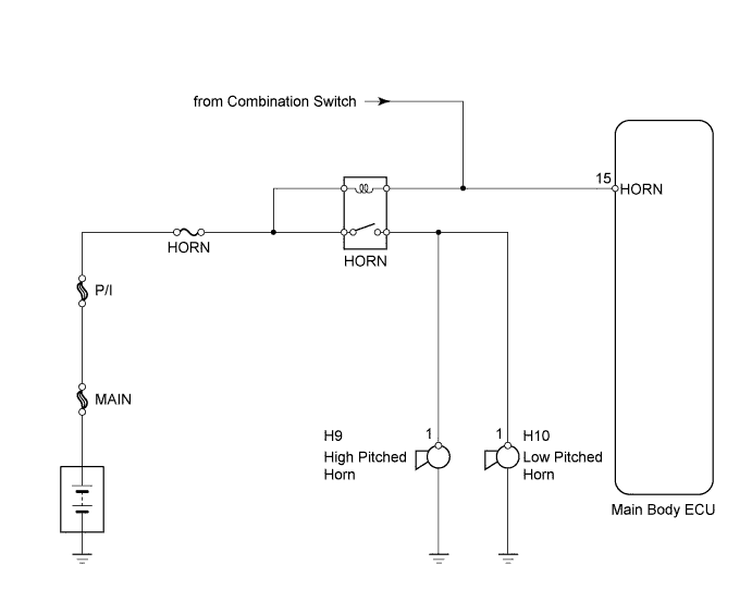
THEFT DETERRENT SYSTEM > Horn Circuit |
| 1.PERFORM ACTIVE TEST USING TECHSTREAM (VEHICLE HORN) |
Select the Active Test, use Techstream (with CAN VIM) to generate a command, and then check the vehicle horns operation.
| Tester Display | Test Part | Control Range | Diagnostic Note |
| Vehicle Horn | Vehicle horns | ON / OFF | - |
|
| ||||
| NG | |
 |
| 2.CHECK HORN |
Press the horn switch and check if the vehicle horns sound.
|
| ||||
| NG | |
|
| 3.INSPECT FUSE (HORN) |
Remove the HORN fuse from the engine room junction block.
Measure the resistance of the fuse.
|
| ||||
| OK | |
|
| 4.CHECK HORN (HORN BATTERY VOLTAGE) |
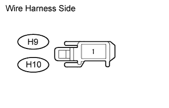 |
Disconnect the H9 and H10 horn connectors.
Measure the voltage of the wire harness side connectors.
| Tester Connection | Condition | Specified Condition |
| H9-1 - Body ground | Horn switch pushed | 10 to 14 V |
| H10-1 - Body ground |
|
| ||||
| NG | |
|
| 5.CHECK WIRE HARNESS (ENGINE ROOM JUNCTION BLOCK - BATTERY) |
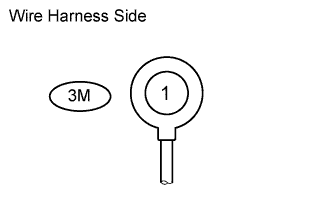 |
Disconnect the 3M junction block connector.
Measure the voltage of the wire harness side connector.
| Tester Connection | Specified Condition |
| 3M-1 - Body ground | 10 to 14 V |
|
| ||||
| OK | |
|
| 6.CHECK WIRE HARNESS (ENGINE ROOM JUNCTION BLOCK - HORN AND BODY GROUND) |
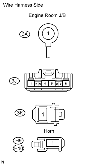 |
Disconnect the 3A, 3K and 3J junction block connectors.
Disconnect the H9 and H10 horn connectors.
Measure the resistance of the wire harness side connectors.
| Tester Connection | Specified Condition |
| 3A-1 - 3K-1 | Below 1 Ω |
| 3J-8 - H9-1 | |
| 3J-8 - H10-1 | |
| 3A-1 or 3K-1 - Body ground | 10 kΩ or higher |
| 3J-8 or H9-1 - Body ground | |
| 3J-8 or H10-1 - Body ground |
|
| ||||
| OK | |
|
| 7.CHECK DRIVER SIDE JUNCTION BLOCK ASSEMBLY (OPERATION) |
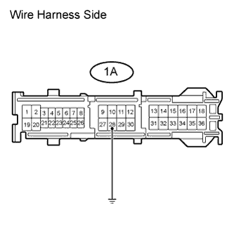 |
Check that the horns sound.
| Connection | Specified Condition |
| Junction block terminal 1A-28 and Body ground connected | Horns sound |
| Horns do not sound |
|
| ||||
| NG | |
|
| 8.CHECK WIRE HARNESS (DRIVER SIDE JUNCTION BLOCK - ENGINE ROOM JUNCTION BLOCK AND BODY GROUND) |
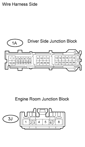 |
Disconnect the 1A and 3A junction block connectors.
Measure the resistance of the wire harness side connectors.
| Tester Connection | Specified Condition |
| 1A-28 - 3J-7 | Below 1 Ω |
| 1A-28 or 3J-7 - Body ground | 10 kΩ or higher |
|
| ||||
| OK | ||
 | ||
| ||
