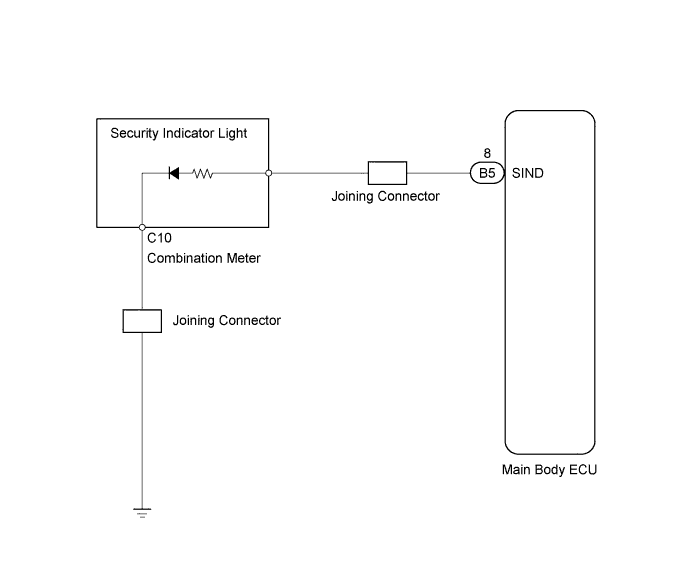
THEFT DETERRENT SYSTEM > Security Indicator Light Circuit |
| 1.PERFORM ACTIVE TEST USING TECHSTREAM (SECURITY INDICATOR LIGHT) |
Select the Active Test, use Techstream (with CAN VIM) to generate a command, and then check the security indicator light operation.
| Tester Display | Test Part | Control Range- | Diagnostic Note |
| Security Indicator | Security indicator light | ON/OFF | - |
|
| ||||
| NG | |
 |
| 2.CHECK WIRE HARNESS (JOINING CONNECTOR - MAIN BODY ECU) |
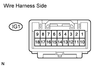 |
Disconnect the IG1 joining connector.
Measure the resistance of the wire harness side connector.
| Tester Connection | Specified Condition |
| IG1-4 - Body ground | Below 1 Ω |
|
| ||||
| OK | |
|
| 3.CHECK WIRE HARNESS (MAIN BODY ECU - JOINING CONNECTOR) |
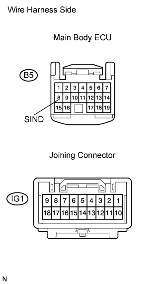 |
Disconnect the B5 ECU connector.
Disconnect the IG1 joining connector.
Measure the resistance of the wire harness side connectors.
| Tester Connection | Specified Condition |
| B5-8 (SIND) - IG1-1 | Below 1 Ω |
| B5-8 (SIND) or IG1-1 - Body ground | 10 kΩ or higher |
|
| ||||
| OK | |
|
| 4.INSPECT COMBINATION METER ECU (SECURITY INDICATOR LIGHT) |
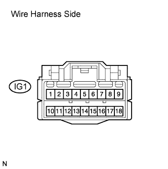 |
Disconnect the IG1 joining connector.
Apply 12 V positive voltage to the terminals of the combination meter.
Check that the security indicator light illuminates.
| Tester Connection | Specified Condition |
| Body positive (+) → Terminal 1 Body negative (-) → Terminal 4 | Illuminates |
|
| ||||
| OK | ||
 | ||
| ||
