 |
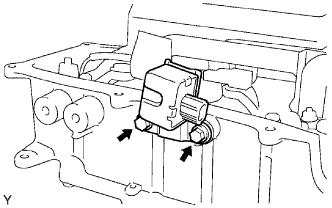
Install the circuit breaker sensor with the 2 bolts.
- Torque:
- 8.0 N*m{ 82 kgf*cm , 71 in.*lbf }
INVERTER WITH CONVERTER > INSTALLATION |
| 1. INSTALL NO. 1 CIRCUIT BREAKER SENSOR |
|
Install the circuit breaker sensor with the 2 bolts.
| 2. INSTALL NO. 2 INVERTER BRACKET |
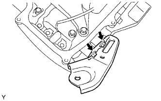 |
Install the inverter bracket with the 2 bolts.
| 3. INSTALL NO. 1 INVERTER BRACKET |
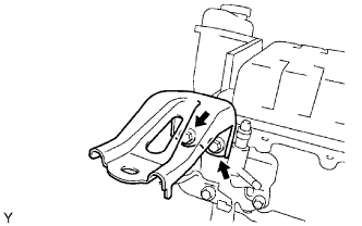 |
Install the inverter bracket with the 2 bolts.
| 4. INSTALL INVERTER WITH CONVERTER ASSEMBLY |
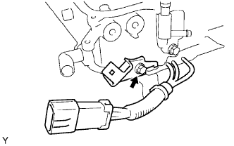 |
Install the connector bracket for the air conditioning inverter with the bolt.
Install the connector for the air conditioning inverter on the bracket.
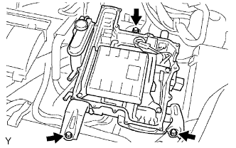 |
Install the inverter with converter assembly with the 3 bolts.
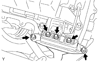 |
Install the MG1 power cable to the MG1 power cable terminal with the 5 bolts.
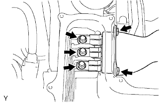 |
Install the MG2 power cable to the MG2 power cable terminal with the 3 bolts.
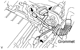 |
Connect the 3 connectors shown in the illustration.
Insert the grommet of the engine main wire harness into the U-shaped groove of the inverter case.
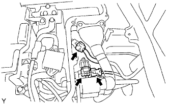 |
Connect the 3 connectors shown in the illustration.
Connect the connector for the air conditioning inverter, then lock the connector with the lock pin.
| 5. CONNECT FRAME WIRE |
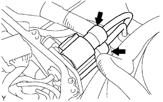 |
Connect the 2 frame wire connectors to the inverter with converter assembly.
| 6. CONNECT NO. 1 CIRCUIT BREAKER SENSOR |
| 7. CONNECT NO. 6 INVERTER COOLING HOSE |
| 8. CONNECT NO. 1 INVERTER COOLING HOSE |
| 9. CONNECT NO. 2 INVERTER COOLING HOSE |
| 10. INSTALL INVERTER COVER |
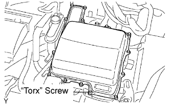 |
Temporarily fasten the inverter cover with the 12 bolts and "torx" screw.
Tighten the 12 bolts.
Using a T30 "torx" socket, tighten the "torx" screw.
| 11. INSTALL RADIATOR SUPPORT OPENING COVER |
| 12. INSTALL FRONT COWL TOP PANEL OUTER |
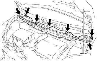 |
Install the panel with the 7 bolts.
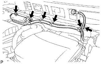 |
Connect the 4 wire harness clamps.
Install the No. 2 engine room relay block with the 2 bolts.
| 13. INSTALL WINDSHIELD WIPER LINK AND WIPER MOTOR ASSEMBLY |
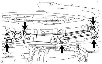 |
Install the windshield wiper motor & link with the 5 bolts.
Connect the connector.
| 14. INSTALL COWL TOP VENTILATOR LOUVER RH |
| 15. INSTALL COWL TOP VENTILATOR LOUVER LH |
| 16. INSTALL HOOD TO COWL TOP SEAL |
| 17. INSTALL FRONT WIPER ARM LH |
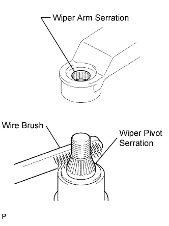 |
Clean the wiper arm serration with a round file or equivalent (when reinstalling).
Clean the wiper pivot serration with a wire brush.
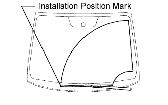 |
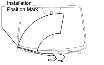
Install the front wiper arm LH with the nut so that the front wiper blade comes to the position shown in the illustration.
| 18. INSTALL FRONT WIPER ARM RH |
 |
Clean the wiper arm serration with a round file or equivalent (when reinstalling).
Clean the wiper pivot serration with a wire brush.
Install the front wiper arm RH with the 2 nuts so that the front wiper blade comes to the position shown in the illustration.
Operate the front wipers while spraying water or washer fluid on the windshield glass. Ensure that the wipers function properly and there is no interference with the body.
| 19. INSTALL WINDSHIELD WIPER ARM COVER |
| 20. INSTALL SERVICE PLUG GRIP |
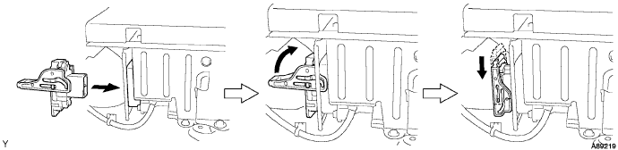
Joint the service plug grip with the HV battery.
While pushing the service plug grip to the right, rotate the lever to the right.
Slide the lever down to lock the service plug grip in place.
| 21. CONNECT CABLE TO NEGATIVE BATTERY TERMINAL |
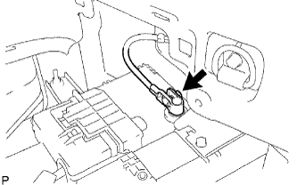 |
Connect the battery negative cable, and then tighten the nut.
| 22. INSTALL REAR NO. 3 FLOOR BOARD |
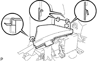 |
Install the floor board, and then attach the 4 claws.
| 23. INSTALL REAR DECK FLOOR BOX |
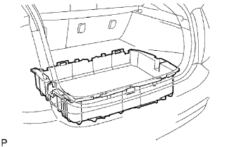 |
Install the rear deck floor box to the vehicle.
| 24. INSTALL REAR NO. 2 FLOOR BOARD |
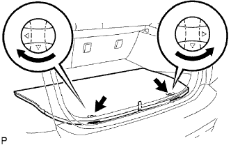 |
Install the floor board, and then lock the 2 cover knobs.
| 25. ADD COOLANT (for Inverter) |
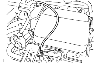 |
Loosen the bleeder plug shown in the illustration and connect a hose.
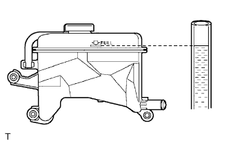 |
Add coolant until the level of coolant in the hose attached to the bleeder tank reaches the same level as the FULL line of the reserve tank.
Close the bleeder plug.
Turn the power switch ON (IG) and run the water pump for approximately 20 seconds.
Turn the power switch OFF. (*1)
Loosen the bleeder plug and bleed the air from the transaxle. (*2)
Add coolant into the bleeder tank. (*3)
Repeat the steps *1, *2 and *3.
Turn the power switch ON (IG) and run the water pump for approximately 5 minutes after completing air bleeding of the coolant system.
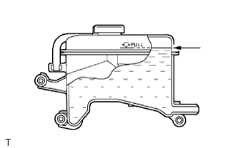 |
Add coolant until the reserve tank is filled up to the FULL mark.
| 26. INSPECT FOR COOLANT LEAK (for Inverter) |
| 27. INSTALL ENGINE UNDER COVER RH |
| 28. INSTALL ENGINE UNDER COVER LH |
| 29. PERFORM INITIALIZATION |
Perform initialization (Click here).