 |
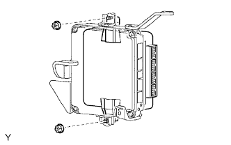
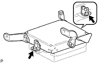
Install the hybrid vehicle control ECU with the 2 nuts.
- Torque:
- 5.5 N*m{ 56 kgf*cm , 49 in.*lbf }
HYBRID VEHICLE CONTROL ECU > INSTALLATION |
| 1. INSTALL HYBRID VEHICLE CONTROL ECU |
|
Install the hybrid vehicle control ECU with the 2 nuts.
| 2. INSTALL ECM |
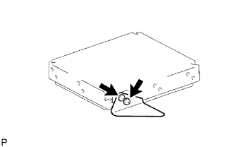 |
Install the No. 3 ECM bracket with the 2 screws.
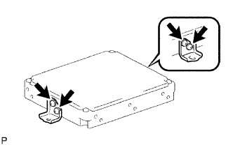 |
Install the 2 No. 2 ECM brackets with the 4 screws.
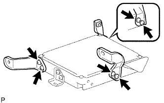 |
Install the 3 No. 1 ECM brackets with the 6 screws.
 |
Install the ECM with the 2 nuts.
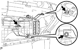 |
Install the ECM with bracket with the 2 nuts and bolt.
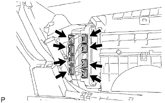 |
Connect the 4 hybrid vehicle control ECU connectors.
Connect the 4 ECM connectors.
| 3. INSTALL NO. 3 HEATER TO REGISTER DUCT |
Install the clip and then the duct with the No. 2 side defroster nozzle duct.
| 4. INSTALL INSTRUMENT PANEL SUB-ASSEMBLY |
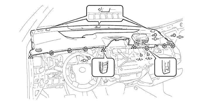
Attach the 6 claws and 3 clips to install the instrument panel.
Install the 2 bolts.
Install the 3 screws.
| 5. CONNECT AIRBAG CONNECTOR |
| 6. INSTALL FRONT PILLAR GARNISH RH |
| 7. INSTALL FRONT PILLAR GARNISH LH |
| 8. INSTALL FRONT PILLAR GARNISH CORNER PIECE RH |
| 9. INSTALL FRONT PILLAR GARNISH CORNER PIECE LH |
| 10. INSTALL NO. 1 INSTRUMENT PANEL SPEAKER PANEL |
| 11. INSTALL GLOVE COMPARTMENT DOOR |
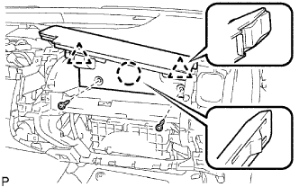 |
Attach the claw and 2 clips to install the glove compartment door.
Install the 2 screws.
| 12. INSTALL GLOVE COMPARTMENT DOOR ASSEMBLY |
Attach the 2 hinges to install the door.
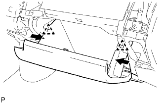 |
While pushing in the sides of the glove compartment door as indicated by the arrows in the illustration, engage it to the 2 stoppers.
| 13. INSTALL GLOVE COMPARTMENT DOOR STOPPER |
| 14. INSTALL MULTI-DISPLAY ASSEMBLY |
| 15. INSTALL NO. 2 INSTRUMENT PANEL REGISTER |
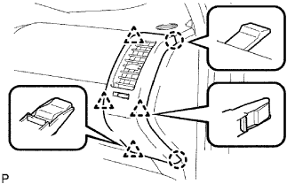 |
Attach the 2 claws and 4 clips to install the instrument panel register.
| 16. INSTALL NO. 4 INSTRUMENT PANEL REGISTER |
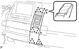 |
Attach the 6 clips to install the instrument panel register.
| 17. INSTALL NO. 3 INSTRUMENT PANEL REGISTER |
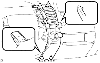 |
Connect the connector.
Attach the claw and 5 clips to install the instrument panel register.
| 18. INSTALL UPPER INSTRUMENT PANEL FINISH PANEL |
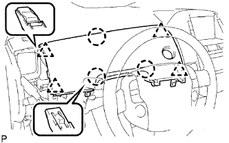 |
Connect the connector.
Attach the 3 claws and 4 clips to install the instrument panel finish panel.
| 19. INSTALL LOWER INSTRUMENT PANEL FINISH PANEL |
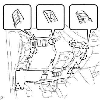 |
Connect the connectors.
Attach the 4 claws and 5 clips to install the instrument panel finish panel.
Connect the hood lock control cable.
Install the 2 screws.
| 20. INSTALL NO. 1 INSTRUMENT PANEL REGISTER |
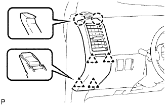 |
Attach the 2 claws and 4 clips to install the instrument panel register.
| 21. CONNECT CABLE TO NEGATIVE BATTERY TERMINAL |
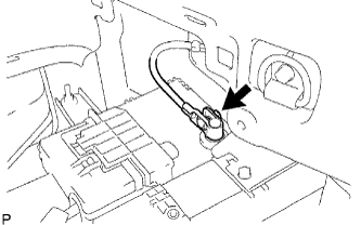 |
Connect the battery negative cable, and then tighten the nut.
| 22. CHECK SRS WARNING LIGHT |
| 23. INSTALL REAR NO. 3 FLOOR BOARD |
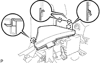 |
Install the floor board, and then attach the 4 claws.
| 24. INSTALL REAR DECK FLOOR BOX |
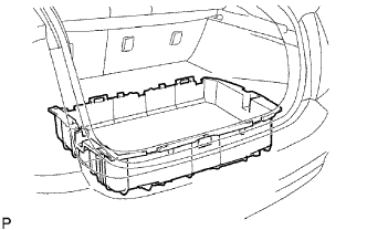 |
Install the rear deck floor box to the vehicle.
| 25. INSTALL REAR NO. 2 FLOOR BOARD |
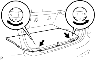 |
Install the floor board, and then lock the 2 cover knobs.
| 26. PERFORM INITIALIZATION |
Perform initialization (Click here).