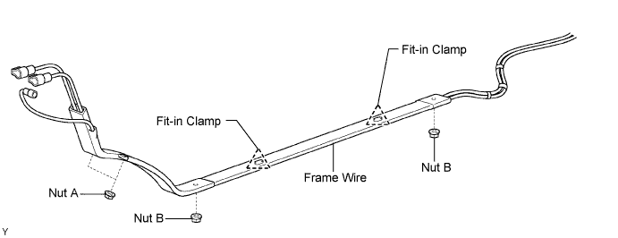
Install both nuts labeled B shown in the illustration.
- Torque:
- 9.0 N*m{ 92 kgf*cm , 80 in.*lbf }
FRAME WIRE > INSTALLATION |
| 1. INSTALL FRAME WIRE |
Temporarily fasten the frame wire to the vehicle.
Connect the fit-in clamps to the stud in the floor panel, and then install the frame wire with both nuts labeled A.
Install both nuts labeled B shown in the illustration.
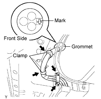 |
As shown in the illustration, point the arrow on the grommet in the front direction, then install the grommet.
Install the 2 bolts.
Install the 2 clamps.
| 2. INSTALL FRONT SUSPENSION CROSSMEMBER |
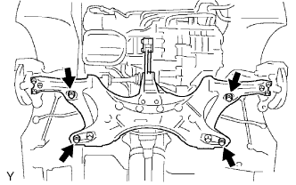 |
Install the front suspension crossmember with the 4 bolts.
Remove the jack.
| 3. INSTALL NO. 1 WIRE HARNESS PROTECTOR |
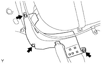 |
Install the wire harness protector with the 2 bolts and nut.
| 4. INSTALL FRONT FLOOR COVER CENTER LH |
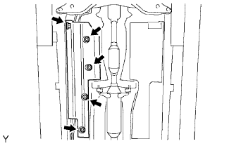 |
Install the floor cover with the 5 clips.
| 5. INSTALL FRONT FLOOR COVER LH |
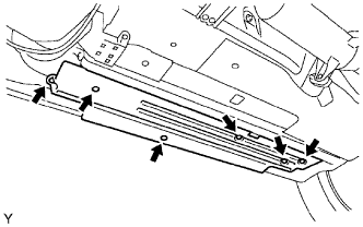 |
Install the floor cover with the 6 clips.
| 6. INSTALL NO. 3 ENGINE UNDER COVER |
| 7. INSTALL NO. 4 ENGINE UNDER COVER CENTER |
| 8. INSTALL STEERING INTERMEDIATE SHAFT |
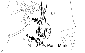 |
Align the paint marks, then connect the steering sliding yoke with the bolt.
Install the column hole cover silencer sheet with the 2 clips.
Remove the seat belt from the steering wheel.
| 9. INSTALL COLUMN HOLE COVER SILENCER SHEET |
| 10. INSTALL FRAME WIRE |
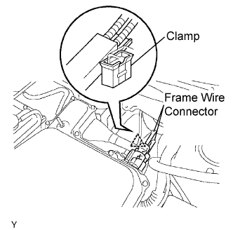 |
Connect the 2 connectors shown in the illustration to the inverter with converter assembly.
Connect the clamp to the engine room relay block with the nut.
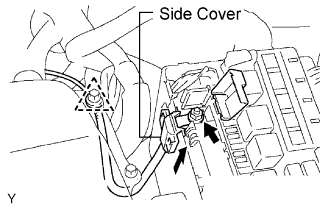 |
Install the frame wire to the engine room relay block with the nut.
Install the side cover to the engine room relay block.
Install the frame wire clamp to the side member.
| 11. INSTALL FRONT COWL TOP PANEL OUTER |
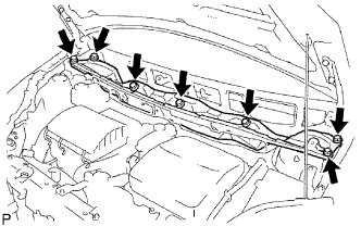 |
Install the panel with the 7 bolts.
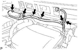 |
Connect the 4 wire harness clamps.
Install the No. 2 engine room relay block with the 2 bolts.
| 12. INSTALL FRONT WIPER LINK AND WIPER MOTOR ASSEMBLY |
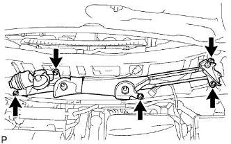 |
Install the windshield wiper motor & link with the 5 bolts.
Connect the connector.
| 13. INSTALL COWL TOP VENTILATOR LOUVER RH |
| 14. INSTALL COWL TOP VENTILATOR LOUVER LH |
| 15. INSTALL HOOD TO COWL TOP SEAL |
| 16. INSTALL FRONT WIPER ARM LH |
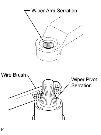 |
Clean the wiper arm serration with a round file or equivalent (when reinstalling).
Clean the wiper pivot serration with a wire brush.
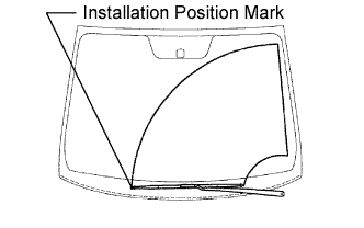 |
Install the front wiper arm LH with the nut so that the front wiper blade comes to the position shown in the illustration.
| 17. INSTALL FRONT WIPER ARM RH |
 |
Clean the wiper arm serration with a round file or equivalent (when reinstalling).
Clean the wiper pivot serration with a wire brush.
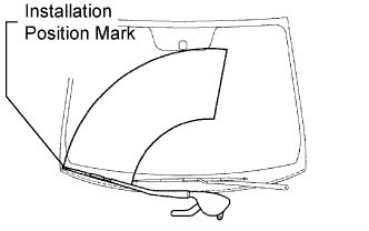
Install the front wiper arm RH with the 2 nuts so that the front wiper blade comes to the position shown in the illustration.
Operate the front wipers while spraying water or washer fluid on the windshield glass. Ensure that the wipers function properly and there is no interference with the body.
| 18. INSTALL FRONT WIPER ARM COVER |
| 19. INSTALL FRAME WIRE |
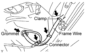 |
Connect the grommet.
Connect the connector.
Install the 2 clamps, then connect the frame wire to the center floor panel.
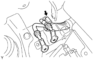 |
Install the frame wire to the rear floor panel with the clamp.
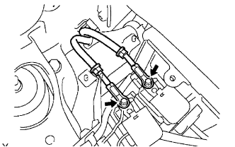 |
Install the frame wire to the No. 2 and No. 3 system main relay with 2 new nuts.
| 20. INSTALL JUNCTION TERMINAL |
| 21. INSTALL NO. 6 BATTERY CARRIER PANEL |
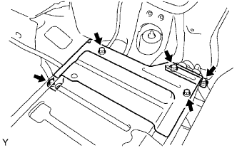 |
Install the battery carrier panel with the bolt and 2 nuts.
| 22. INSTALL FLOOR SIDE PANEL LH |
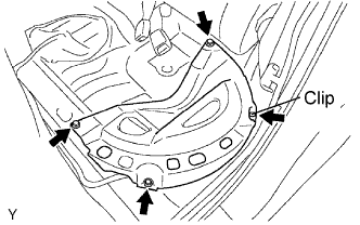 |
Install the clip.
Install the floor side panel with the 3 bolts.
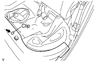 |
Install the carpet with the clip.
| 23. INSTALL REAR DOOR SCUFF PLATE LH |
| 24. INSTALL BATTERY CARRIER BRACKET |
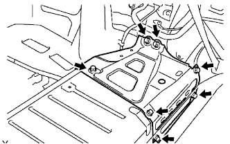 |
Install the battery carrier bracket with the 7 bolts.
| 25. INSTALL DECK TRIM SIDE PANEL LH |
Connect the lighting connector.
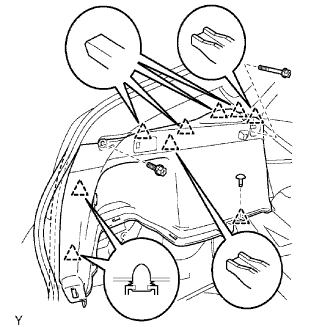 |
Install the deck trim side panel with the 8 clips and 2 bolts, and then install the part of the weather strip.
Install the luggage hold belt striker with the bolt.
| 26. INSTALL DECK FLOOR BOX LH |
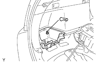 |
Install the deck floor box with the clip.
| 27. INSTALL REAR NO. 4 FLOOR BOARD |
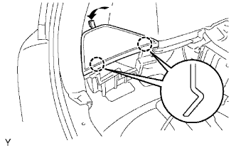 |
| 28. INSTALL REAR SIDE SEATBACK FRAME LH |
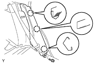 |
Install the seat back frame with the bolt.
| 29. INSTALL REAR NO. 1 FLOOR BOARD |
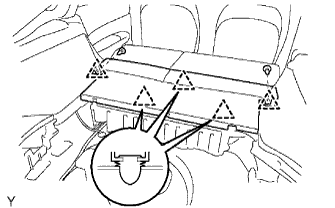 |
Install the floor board.
Install the 2 luggage strikers with the 2 bolts.
| 30. INSTALL REAR SEAT CUSHION ASSEMBLY |
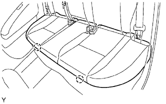 |
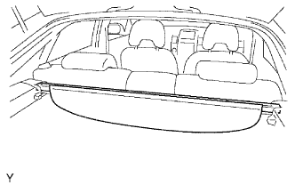
| 31. INSTALL TONNEAU COVER |
 |
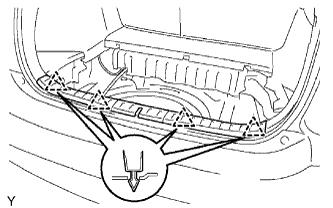
| 32. INSTALL REAR DECK TRIM COVER |
 |
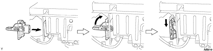
| 33. INSTALL SERVICE PLUG GRIP |
Joint the service plug grip with the HV battery.
While pushing the service plug grip to the right, rotate the lever to the right.
Slide the lever down to lock the service plug grip in place.
| 34. CONNECT CABLE TO NEGATIVE BATTERY TERMINAL |
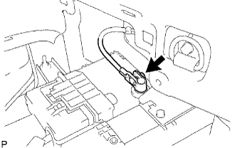 |
Connect the battery negative cable, and then tighten the nut.
| 35. INSTALL REAR NO. 3 FLOOR BOARD |
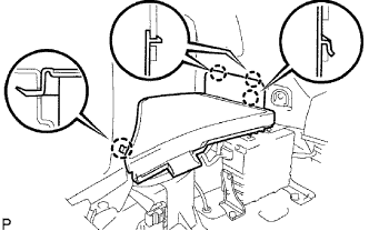 |
Install the floor board, and then attach the 4 claws.
| 36. INSTALL REAR DECK FLOOR BOX |
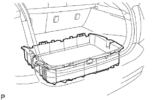 |
Install the rear deck floor box to the vehicle.
| 37. INSTALL REAR NO. 2 FLOOR BOARD |
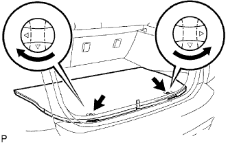 |
Install the floor board, and then lock the 2 cover knobs.
| 38. INSTALL FRONT WHEEL |
| 39. PERFORM INITIALIZATION |
Perform initialization (Click here).