 |
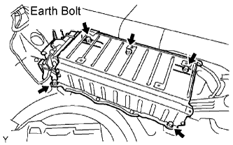
Install the HV battery with the earth bolt and 4 bolts.
- Torque:
- 19 N*m{ 194 kgf*cm , 14 in.*lbf }
HV BATTERY > INSTALLATION |
| 1. INSTALL HV BATTERY ASSEMBLY |
|
Install the HV battery with the earth bolt and 4 bolts.
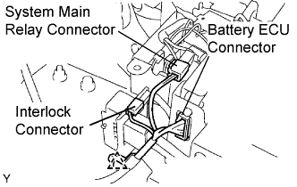 |
Connect the system main relay connector.
Connect the interlock connector.
Connect the battery ECU connector.
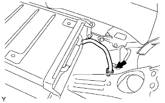 |
Connect the battery room ventilation hose to the floor panel.
| 2. INSTALL FRAME WIRE |
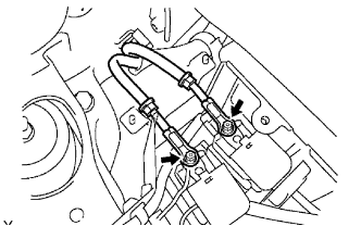 |
Install the frame wire on the No. 2 and No. 3 system main relay with 2 new nuts.
Connect the 2 clamps, then install the frame wire to the upper battery carrier.
| 3. INSTALL JUNCTION TERMINAL |
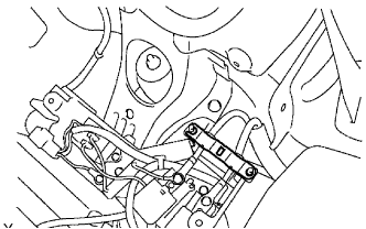 |
| 4. INSTALL NO. 6 BATTERY CARRIER PANEL |
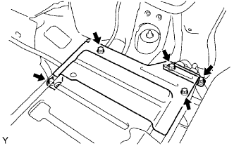 |
Install the battery carrier panel with the bolt and 2 nuts.
| 5. INSTALL QUARTER VENT DUCT |
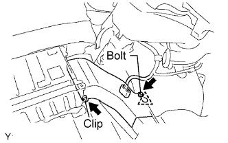 |
Install the quarter vent duct with the bolt and clip.
Connect the connector.
Install the clamp.
| 6. INSTALL BATTERY BRACKET REINFORCEMENT |
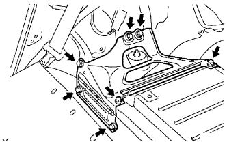 |
Install the battery bracket reinforcement with the 7 bolts.
| 7. INSTALL NO. 2 QUARTER VENT DUCT INNER |
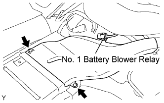 |
Insert the quarter vent duct inner until it touches the backside of the HV battery.
Slide the fitting surface of the quarter vent duct inner downward, then attach it to the battery blower assembly.
Install the 2 clips on the vent duct.
Install the battery blower relay.
| 8. INSTALL BATTERY CARRIER BRACKET |
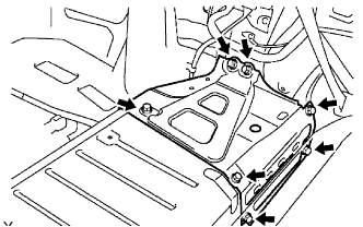 |
Install the battery carrier bracket with the 7 bolts.
| 9. INSTALL DECK TRIM SIDE PANEL RH |
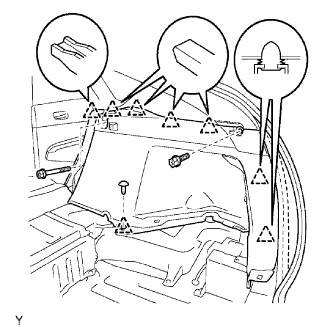 |
Install the deck trim side panel with the 7 clips and 2 bolts, and then install the part of the weather strip.
Install the luggage hold belt striker with the bolt.
| 10. INSTALL DECK TRIM SIDE PANEL LH |
Connect the lighting connector.
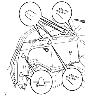 |
Install the deck trim side panel with the 8 clips and 2 bolts, and then install the part of the weather strip.
Install the luggage hold belt striker with the bolt.
| 11. INSTALL DECK FLOOR BOX LH |
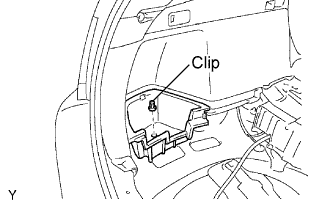 |
Install the deck floor box with the clip.
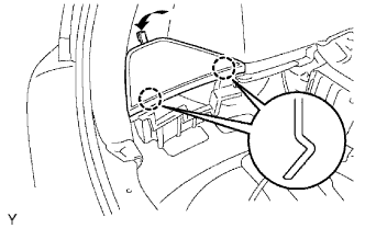
| 12. INSTALL REAR NO. 4 FLOOR BOARD |
 |
| 13. INSTALL REAR SIDE SEAT BACK FRAME RH |
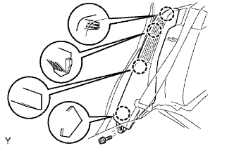 |
Install the seat back frame with the bolt.
| 14. INSTALL REAR SIDE SEAT BACK FRAME LH |
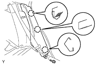 |
Install the seat back frame with the bolt.
| 15. INSTALL REAR NO. 1 FLOOR BOARD |
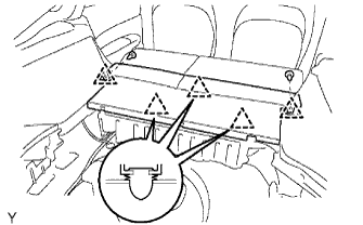 |
Install the floor board.
Install the 2 luggage strikers with the 2 bolts.
| 16. INSTALL REAR SEAT CUSHION ASSEMBLY |
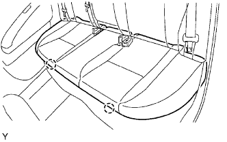 |
| 17. INSTALL TONNEAU COVER |
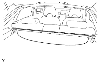 |
| 18. INSTALL REAR DECK TRIM COVER |
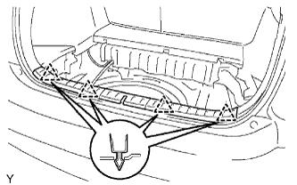 |
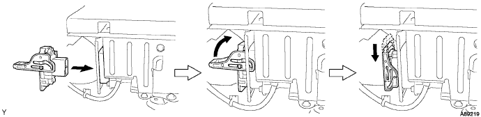
| 19. INSTALL SERVICE PLUG GRIP |
Joint the service plug grip with the HV battery.
While pushing the service plug grip to the right, rotate the lever to the right.
Slide the lever down to lock the service plug grip in place.
| 20. CONNECT CABLE TO NEGATIVE BATTERY TERMINAL |
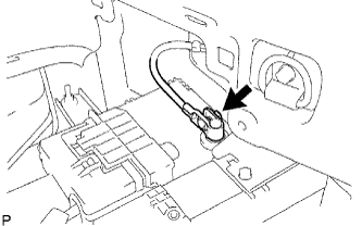 |
Connect the battery negative cable, and then tighten the nut.
| 21. INSTALL REAR NO. 3 FLOOR BOARD |
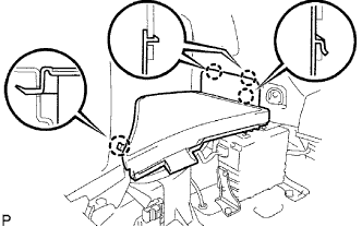 |
Install the floor board, and then attach the 4 claws.
| 22. INSTALL REAR DECK FLOOR BOX |
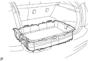 |
Install the rear deck floor box to the vehicle.
| 23. INSTALL REAR NO. 2 FLOOR BOARD |
|
Install the floor board, and then attach the 4 claws.
| 24. PERFORM INITIALIZATION |
Perform initialization (Click here).