 |
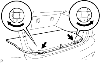
Unlock the 2 washer tank cover knobs, and then remove the rear floor board.
HV BATTERY > REMOVAL |
| 1. PRECAUTION |
| 2. REMOVE REAR NO. 2 FLOOR BOARD |
|
Unlock the 2 washer tank cover knobs, and then remove the rear floor board.
| 3. REMOVE REAR DECK FLOOR BOX |
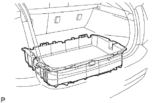 |
Remove the rear deck floor box from the vehicle.
| 4. REMOVE REAR NO. 3 FLOOR BOARD |
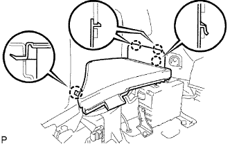 |
Detach the 4 claws, and then remove the floor board.
| 5. DISCONNECT CABLE FROM NEGATIVE BATTERY TERMINAL |
| 6. REMOVE SERVICE PLUG GRIP |
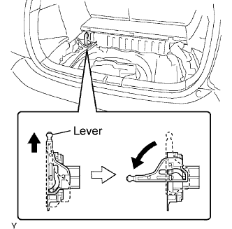 |
Slide up the lever of the service plug grip. Remove the service plug grip while turning the lever to the left.
Insulate the service plug with insulating tape.
| 7. REMOVE REAR DECK TRIM COVER |
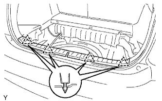 |
Detach the 4 clips shown in the illustration, then remove the deck trim cover.
| 8. REMOVE TONNEAU COVER |
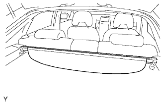 |
Remove the tonneau cover from the vehicle.
| 9. REMOVE REAR SEAT CUSHION ASSEMBLY |
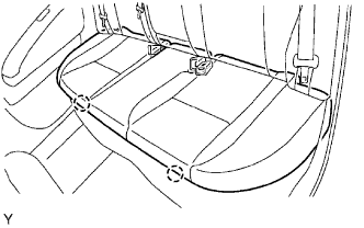 |
Undo the 2 joints shown in the illustration, then remove the rear seat cushion.
| 10. REMOVE REAR NO. 1 FLOOR BOARD |
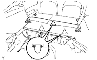 |
Remove the 2 bolts and luggage hold belt strikers.
Remove the 5 clips shown in the illustration and the rear floor board.
| 11. REMOVE REAR SIDE SEAT BACK FRAME LH |
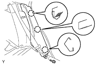 |
Remove the bolt from the rear side seat back frame LH.
Undo the 3 joints, then remove the rear side seat back frame LH.
| 12. REMOVE REAR SIDE SEAT BACK FRAME RH |
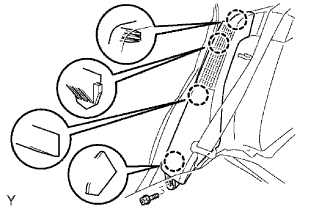 |
Remove the bolt from the rear side seat back frame RH.
Undo the 4 joints, then remove the rear side seat back frame RH.
| 13. REMOVE REAR NO. 4 FLOOR BOARD |
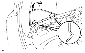 |
While lifting up the rear floor board as shown in the illustration, undo the 2 joints and remove the rear floor board.
| 14. REMOVE DECK FLOOR BOX LH |
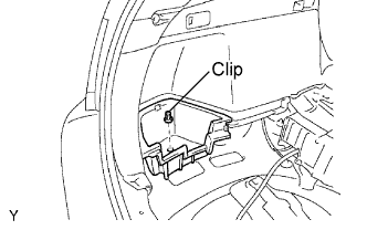 |
Remove the clip and deck floor box LH.
| 15. REMOVE DECK TRIM SIDE PANEL LH |
Remove the bolt and luggage hold belt striker.
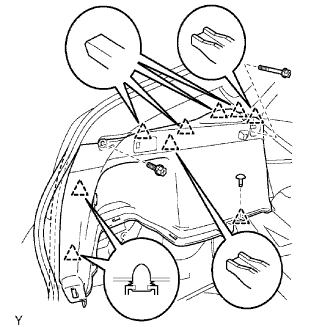 |
Remove the 2 bolts from the deck trim side panel LH.
Remove the clip from the deck trim side panel LH.
Undo the 8 clips, then pull out a part of the weather strip and remove the deck trim side panel LH.
Disconnect the lighting connector.
| 16. REMOVE DECK TRIM SIDE PANEL RH |
Remove the bolt and luggage hold belt striker.
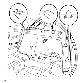 |
Remove the 2 bolts from the deck trim side panel RH.
Remove the clip from the deck trim side panel RH.
Undo the 7 clips, then pull out a part of the weather strip and remove the deck trim side panel RH.
| 17. REMOVE BATTERY CARRIER BRACKET |
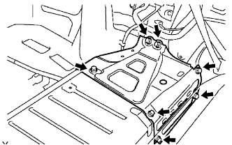 |
Remove the 7 bolts and battery carrier bracket.
| 18. REMOVE NO. 2 QUARTER VENT DUCT INNER |
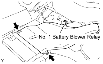 |
Disconnect the clamp and No. 1 battery blower relay.
Remove the 2 clips.
Slide the vent duct to the battery side, then remove it.
| 19. REMOVE BATTERY BRACKET REINFORCEMENT |
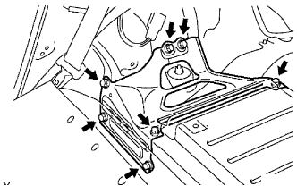 |
Remove the 7 bolts and battery bracket reinforcement.
| 20. REMOVE QUARTER VENT DUCT |
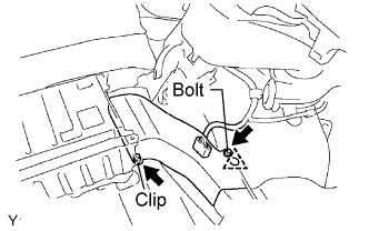 |
Disconnect the connector.
Remove the clamp, then disconnect the wire harness.
Remove the bolt, clip and quarter vent duct.
| 21. REMOVE NO. 6 BATTERY CARRIER PANEL |
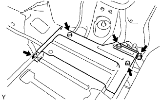 |
Remove the 3 bolts, 2 nuts and battery carrier panel.
| 22. REMOVE JUNCTION TERMINAL |
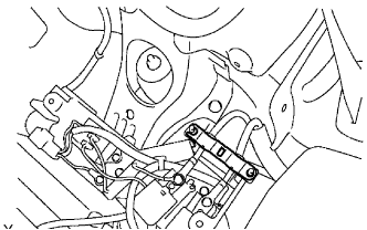 |
| 23. REMOVE FRAME WIRE |
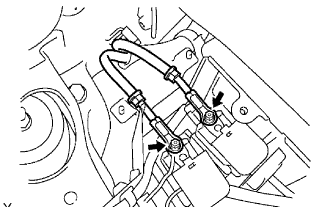 |
Remove the 2 nuts, then disconnect the frame wire from the No. 2 and No. 3 system main relay.
| 24. REMOVE HV BATTERY ASSEMBLY |
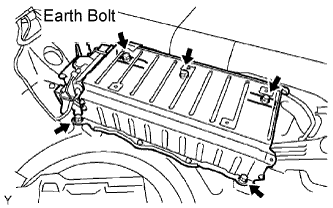 |
Remove the earth bolt and 4 bolts shown in the illustration.
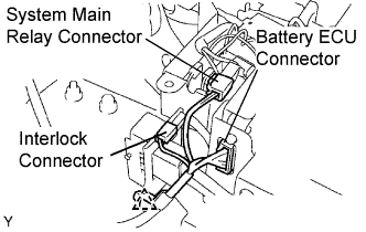 |
Disconnect the system main relay connector.
Disconnect the interlock connector.
Remove the clamp, then disconnect the battery ECU connector.
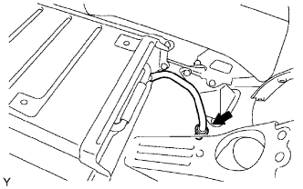 |
Disconnect the battery room ventilation hose from the floor panel.
Remove the HV battery.