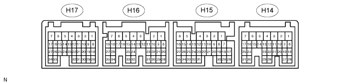
CRUISE CONTROL SYSTEM > TERMINALS OF ECU |
| CHECK HYBRID VEHICLE CONTROL ECU |
Measure the voltage of the connectors.
| Symbols (Terminals No.) | Wiring Color | Terminal Description | Condition | Specified Condition |
| ST1- (H15-2) - GND1 (H14-1) | G - W-B | Stop light signal | Power switch is ON (IG), depress brake pedal | Below 1 V |
| Power switch is ON (IG), release brake pedal | 10 to 14 V | |||
| STP (H15-3) - GND1 (H14-1) | L - W-B | Power switch is ON (IG), depress brake pedal | 10 to 14 V | |
| Power switch is ON (IG), release brake pedal | Below 1 V | |||
| CCS (H14-13) - GND1 (H14-1) | V - W-B | Cruise control main switch circuit | Power switch is ON (IG) | 10 to 14 V |
| Power switch is ON (IG), CANCEL switch is held on | 6.6 to 10.1 V | |||
| Power switch is ON (IG), -/SET switch is held on | 4.5 to 7.1 V | |||
| Power switch is ON (IG), +/RES switch is held on | 2.3 to 4.0 V | |||
| Power switch is ON (IG), ON-OFF button is pushed on | Below 1 V | |||
| SPDI (H14-19) - GND1 (H14-1) | V - W-B | Vehicle speed input signal | Power switch is ON (IG), slowly turn wheel | Below 1 V to above 5 V |