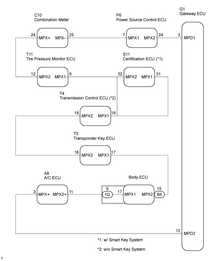
DTC B1214 Short to B+ in Door System Communication Bus Malfunction |
DTC B1215 Short to GND in Door System Communication Bus Malfunction |
| DTC No. | DTC Detection Condition | Trouble Area |
| B1214 | B+ short in BEAN |
|
| B1215 | GND short in BEAN |
| 1.CHECK A/C ECU |
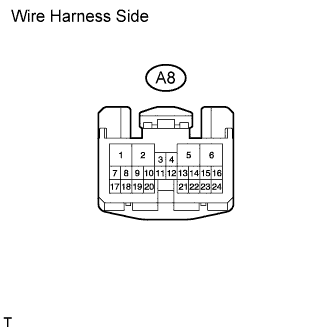 |
Turn the power switch OFF.
Disconnect the A/C ECU connector.
Connect the Techstream to the DLC3.
Turn the power switch ON (IG).
Clear and check DTCs.
| DTC | Conclusion | Proceed to |
| B1214 or B1215 is present | A/C ECU is OK | A |
| B1214 and B1215 are not present | A/C ECU is malfunctioning | B |
|
| ||||
| A | |
 |
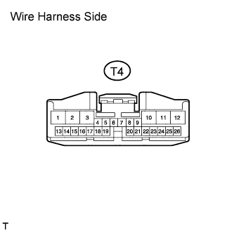
| 2.CHECK TRANSMISSION CONTROL ECU |
 |
Turn the power switch OFF.
Connect the A/C ECU connector.
Disconnect the transmission control ECU connector.
Turn the power switch ON (IG).
Clear and check DTCs.
| DTC | Conclusion | Proceed to |
| B1214 or B1215 is present | Transmission control ECU is OK | A |
| B1214 and B1215 are not present | Transmission control ECU is malfunctioning | B |
|
| ||||
| A | |
|
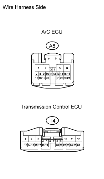
| 3.CHECK WIRE HARNESS (TRANSMISSION CONTROL ECU - A/C ECU) |
 |
Turn the power switch OFF.
Disconnect the transmission control ECU connector and A/C ECU connector.
Turn the power switch ON (IG).
Clear and check DTCs.
| DTC | Conclusion | Proceed to |
| B1214 or B1215 is present | Wire harness is OK | A |
| B1214 and B1215 are not present | Wire harness is short circuited | B |
|
| ||||
| A | |
|
| 4.CHECK POWER SOURCE CONTROL ECU |
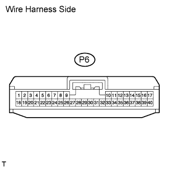 |
Turn the power switch OFF.
Connect the A/C ECU connector and transmission control ECU connector.
Disconnect the power source control ECU connector.
Turn the power switch ON (IG).
Clear and check DTCs.
| DTC | Conclusion | Proceed to |
| B1214 or B1215 is present | Power source control ECU is OK | A |
| B1214 and B1215 are not present | Power source control ECU is malfunctioning | B |
|
| ||||
| A | |
|
| 5.CHECK WIRE HARNESS (POWER SOURCE CONTROL ECU - TRANSMISSION CONTROL ECU) |
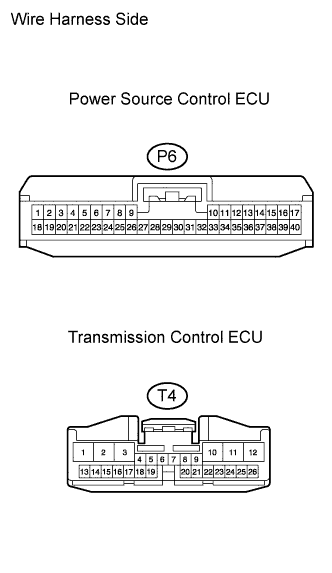 |
Turn the power switch OFF.
Disconnect the power source control ECU connector and transmission control ECU connector.
Turn the power switch ON (IG).
Clear and check DTCs.
| DTC | Conclusion | Proceed to |
| B1214 or B1215 is present | Wire harness is OK | A |
| B1214 and B1215 are not present | Wire harness is short circuited | B |
|
| ||||
| A | |
|
| 6.CHECK WIRE HARNESS (GATEWAY ECU - POWER SOURCE CONTROL ECU) |
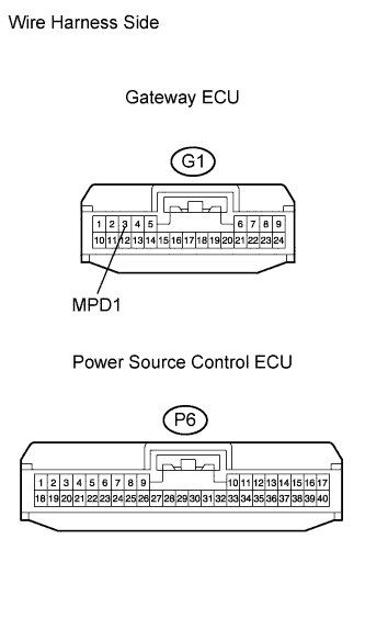 |
Turn the power switch OFF.
Connect the transmission control ECU connector.
Disconnect the power source control ECU connector and gateway ECU connector.
Measure the resistance and voltage of the gateway ECU connector terminal.
| Tester Connection | Specified Condition |
| G1-3 (MPD1) - Body ground | 10 kΩ or higher |
| Tester Connection | Condition | Specified Condition |
| G1-3 (MPD1) - Body ground | Power switch ON (IG) | Below 1 V |
|
| ||||
| OK | |
|
| 7.CHECK WIRE HARNESS (GATEWAY ECU - A/C ECU) |
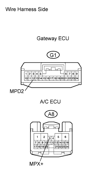 |
Turn the power switch OFF.
Connect the power source control ECU connector.
Disconnect the A/C ECU connector and gateway ECU connector.
Measure the resistance and voltage of the gateway ECU connector terminal.
| Tester Connection | Specified Condition |
| G1-12 (MPD2) - Body ground | 10 kΩ or higher |
| Tester Connection | Condition | Specified Condition |
| G1-12 (MPD2) - Body ground | Power switch ON (IG) | Below 1 V |
|
| ||||
| OK | ||
 | ||
| ||
| 8.CHECK DRIVER SIDE JUNCTION BLOCK |
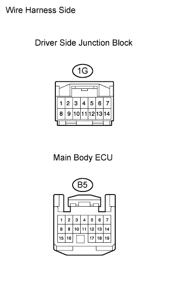 |
Turn the power switch OFF.
Connect the A/C ECU connector and transmission control ECU connector.
Disconnect the 1G driver side junction block connector and B5 main body ECU connector.
Turn the power switch ON (IG).
Clear and check DTCs.
| DTC | Conclusion | Proceed to |
| B1214 or B1215 is present | Driver side junction block is OK | A |
| B1214 and B1215 are not present | Driver side junction block is malfunctioning | B |
|
| ||||
| A | |
|
| 9.CHECK WIRE HARNESS (DRIVER SIDE JUNCTION BLOCK - A/C ECU) |
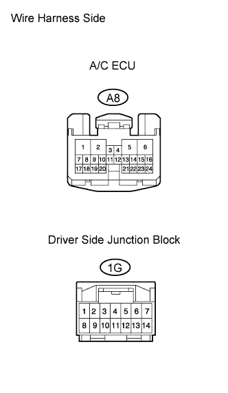 |
Turn the power switch OFF.
Connect the B5 ECU connector.
Disconnect the 1G driver side junction block connector and A/C ECU connector.
Turn the power switch ON (IG).
Clear and check DTCs.
| DTC | Conclusion | Proceed to |
| B1214 or B1215 is present | Wire harness is OK | A |
| B1214 and B1215 are not present | Wire harness is short circuited | B |
|
| ||||
| A | |
|
| 10.CHECK TRANSPONDER KEY ECU |
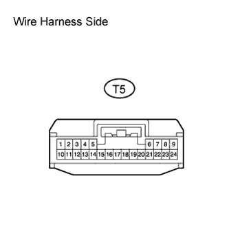 |
Turn the power switch OFF.
Connect the driver side junction block connector and A/C ECU connector.
Disconnect the transponder key ECU connector.
Turn the power switch ON (IG).
Clear and check DTCs.
| DTC | Conclusion | Proceed to |
| B1214 or B1215 is present | Transponder key ECU is OK | A |
| B1214 and B1215 are not present | Transponder key ECU is malfunctioning | B |
|
| ||||
| A | |
|
| 11.CHECK WIRE HARNESS (TRANSPONDER KEY ECU - DRIVER SIDE JUNCTION BLOCK) |
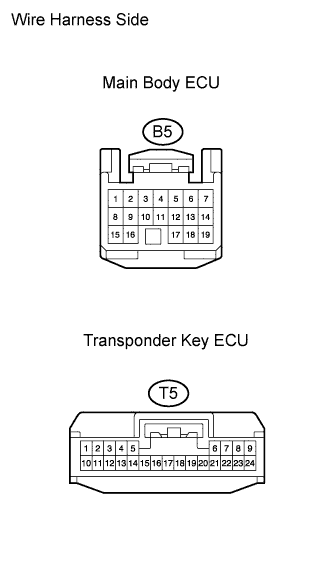 |
Turn the power switch OFF.
Disconnect the transponder key ECU connector and B5 ECU connector.
Turn the power switch ON (IG).
Clear and check DTCs.
| DTC | Conclusion | Proceed to |
| B1214 or B1215 is present | Wire harness is OK | A |
| B1214 and B1215 are not present | Wire harness is short circuited | B |
|
| ||||
| A | ||
| ||
| ||
| 12.CHECK COMBINATION METER |
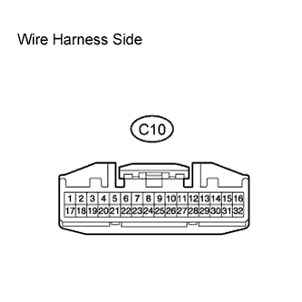 |
Turn the power switch OFF.
Connect the power source control ECU connector and transmission control ECU connector.
Disconnect the C10 meter connector.
Turn the ignition switch ON (IG).
Clear and check DTCs.
| DTC | Conclusion | Proceed to |
| B1214 or B1215 is present | Combination meter is OK | A |
| B1214 and B1215 are not present | Combination meter is malfunctioning | B |
|
| ||||
| A | |
|
| 13.CHECK WIRE HARNESS (COMBINATION METER - POWER SOURCE CONTROL ECU) |
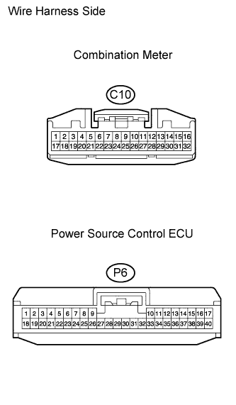 |
Turn the power switch OFF.
Disconnect the C10 combination meter and power source control ECU connector.
Turn the power switch ON (IG).
Clear and check DTCs.
| DTC | Conclusion | Proceed to |
| B1214 or B1215 is present | Wire harness is OK | A |
| B1214 and B1215 are not present | Wire harness is short circuited | B |
|
| ||||
| A | |
|
| 14.CHECK TIRE PRESSURE WARNING ECU |
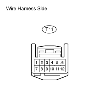 |
Turn the power switch OFF.
Connect the C10 meter connector and power source control ECU connector.
Disconnect the tire pressure monitor ECU connector.
Turn the power switch ON (IG).
Clear and check DTCs.
| DTC | Conclusion | Proceed to |
| B1214 or B1215 is present | Tire pressure monitor ECU is OK | A |
| B1214 and B1215 are not present | Tire pressure monitor ECU is malfunctioning | B |
|
| ||||
| A | |
|
| 15.CHECK WIRE HARNESS (TIRE PRESSURE WARNING ECU - COMBINATION METER) |
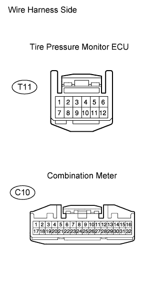 |
Turn the power switch OFF.
Disconnect the tire pressure monitor ECU connector and C10 meter connector.
Turn the power switch ON (IG).
Clear and check DTCs.
| DTC | Conclusion | Proceed to |
| B1214 or B1215 is present | Wire harness is OK | A |
| B1214 and B1215 are not present | Wire harness is short circuited | B |
|
| ||||
| A | |
|
| 16.CONFIRM EQUIPMENT |
| Equipment | Proceed to |
| With smart key system | A |
| Without smart key system | B |
|
| ||||
| A | |
|
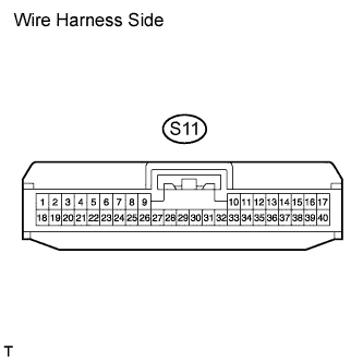
| 17.CHECK CERTIFICATION ECU |
 |
Turn the power switch OFF.
Connect the C10 meter connector and tire pressure monitor ECU connector.
Disconnect the certification ECU connector.
Turn the power switch ON (IG).
Clear and check DTCs.
| DTC | Conclusion | Proceed to |
| B1214 or B1215 is present | Certification ECU is OK | A |
| B1214 and B1215 are not present | Certification ECU is malfunctioning | B |
|
| ||||
| A | |
|
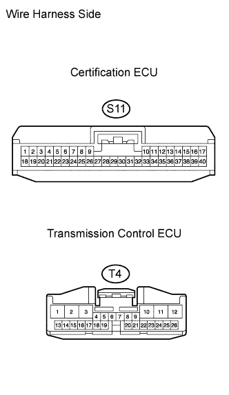
| 18.CHECK WIRE HARNESS (CERTIFICATION ECU - TIRE PRESSURE MONITOR ECU) |
 |
Turn the power switch OFF.
Disconnect the certification ECU connector and tire pressure monitor ECU connector.
Turn the power switch ON (IG).
Clear and check DTCs.
| DTC | Conclusion | Proceed to |
| B1214 or B1215 is present | Wire harness is OK | A |
| B1214 and B1215 are not present | Wire harness is short circuited | B |
|
| ||||
| A | ||
| ||
| ||

