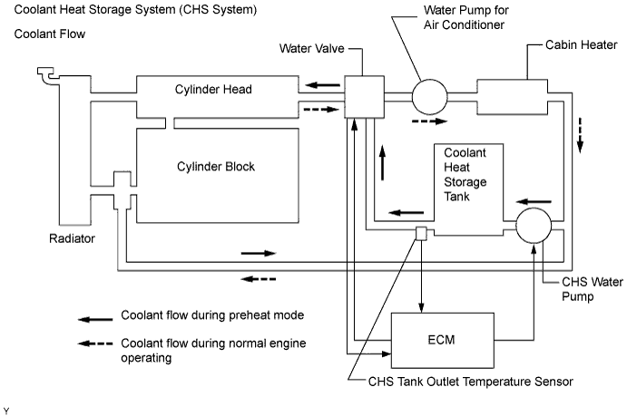
DTC P1120 Coolant Flow Control Valve Position Sensor Circuit |
DTC P1122 Coolant Flow Control Valve Position Sensor Circuit Low |
DTC P1123 Coolant Flow Control Valve Position Sensor Circuit High |
| DTC No. | DTC Detection Condition | Trouble Area |
| P1120 | Water valve position sensor voltage is less than 0.2 V or more than 4.8 V |
|
| P1122 | Water valve position sensor voltage stays less than 0.2 V for 2 seconds or more |
|
| P1123 | Water valve position sensor voltage stays more than 4.8 V for 2 seconds or more |
|
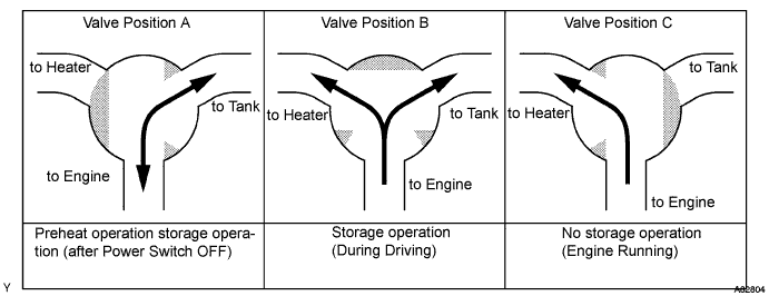
| System Condition | Valve Position | Coolant Flow |
| Normal engine operation | C | Engine to Cabin heater |
| Preheat mode | A | Coolant heat storage tank to Engine |
| Coolant recovering (after engine stop) | A | Engine to Coolant heat storage tank |
| Coolant recovering (while engine is running) | B | Engine to Cabin heater and Coolant heat storage tank |
| Soak mode | A | Coolant heat storage tank to Engine |
| Related DTCs |
|
| Required sensors/components | Water valve position sensor |
| Frequency of operation | Continuous |
| Duration | 2 seconds |
| MIL operation | Immediately |
| Sequence of operation | None |
| The monitor will run whenever the following DTCs are not present | None |
| Water valve position sensor voltage | Less than 0.2 V or more than 4.8 V |
| Water valve position sensor voltage | Less than 0.2 V |
| Water valve position sensor voltage | More than 4.8 V |
| Water valve position sensor voltage | 0.2 to 4.8 V |
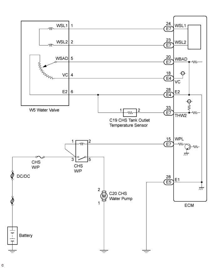
| 1.CHECK ECM (WBAD - E2 VOLTAGE) |
 |
Turn the power switch ON (IG).
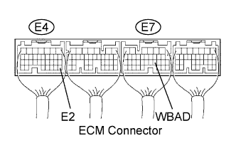
Measure the voltage between the terminals WBAD and E2 of the E4 and E7 ECM connectors.
| Water Valve | Specified Condition |
| Valve position "A" (Preheat mode) | Approximately 2.5 V |
| Valve position "B" (Recovering mode) | Approximately 3.5 V |
| Valve position "C" (Normal Operation) | Approximately 4.5 V |
|
| ||||
| NG | |
 |
| 2.INSPECT WATER M/BRACKET VALVE ASSEMBLY |
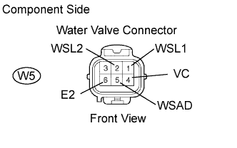 |
Disconnect the W5 water valve connector.
Measure the resistance between terminals WSL1 and WSL2 of the water valve connector.
Measure the resistance between terminals WSAD and E2 of the water valve connector.
| Tester Connection | Specification Condition |
| 1 (WSL1) - 2 (WSL2) | Approximately 0.04 kΩ |
| 5 (WSAD) - 6 (E2) | 0.2 to 5.7 kΩ |
|
| ||||
| OK | |
|
| 3.CHECK HARNESS AND CONNECTOR (WATER VALVE - ECM) |
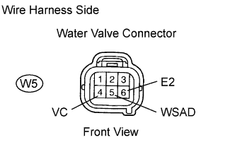 |
Disconnect the W5 water valve connector.
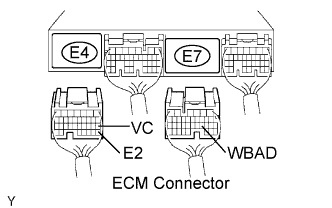 |
Disconnect the E4 and E7 ECM connectors.
Measure the resistance according to the value(s) in the table below.
| Tester Connection | Specified Condition |
| W5-5 (Water valve) - E7-20 (WBAD) | Below 1 Ω |
| W5-4 (Water valve) - E4-18 (VC) | Below 1 Ω |
| W5-6 (Water valve) - E4-28 (E2) | Below 1 Ω |
| Tester Connection | Specified Condition |
| W5-5 (Water valve) or E7-20 (WBAD) - Body ground | 10 kΩ or higher |
Reconnect the water valve connector.
Reconnect the ECM connectors.
|
| ||||
| OK | ||
 | ||
| ||
