 |
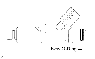
Apply a light coat of spindle oil or gasoline to a new O-ring, then install it to each fuel injector.
FUEL INJECTOR > INSTALLATION |
| 1. INSTALL FUEL INJECTOR ASSEMBLY |
|
Apply a light coat of spindle oil or gasoline to a new O-ring, then install it to each fuel injector.
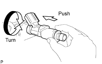 |
Apply a light coat of spindle oil or gasoline to the surface of the fuel delivery pipe which contacts the O-ring of the fuel injector.
Apply a light coat of spindle oil or gasoline to the O-ring again, and install the fuel injector by turning it right and left while pushing it onto the fuel delivery pipe.
Check that the fuel injector rotates smoothly.
If the fuel injector does not rotate, replace the O-ring.
| 2. INSTALL FUEL DELIVERY PIPE |
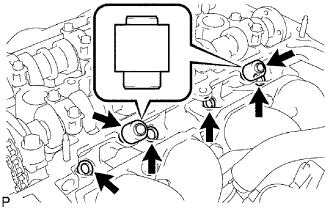 |
Install 4 new insulators to the cylinder head.
Install the 2 No. 1 delivery pipe spacers to the cylinder head.
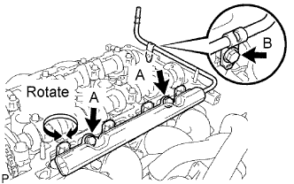 |
Install the fuel delivery pipe together with the 4 fuel injectors, and then temporarily tighten the 3 bolts.
Check that the fuel injectors rotate smoothly.
If the fuel injectors do not rotate, replace the O-ring.
Retighten the 3 bolts to the specified torque.
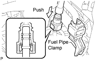 |
Connect the fuel tube to the fuel delivery pipe.
Align the fuel tube connector with the pipe, then push in the fuel tube connector until the retainer makes a "click" sound to connect the fuel tube to the fuel delivery pipe.
Install the No. 1 fuel pipe clamp.
| 3. INSTALL CYLINDER HEAD COVER SUB-ASSEMBLY |
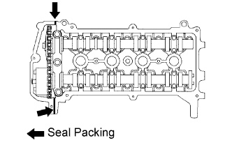 |
Apply seal packing to the 2 locations shown in the illustration, then install the cylinder head cover.
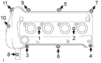 |
Install the cylinder head cover with the 9 bolts and 2 nuts.
Using several steps, tighten the bolts and nuts to the specified torque in the sequence shown in the illustration.
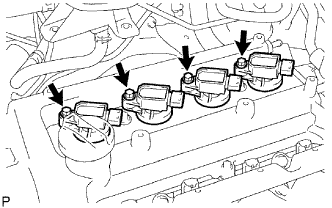 |
Install the ignition coil with the bolt.
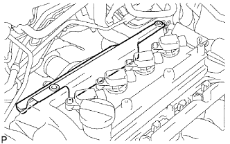 |
Install the brake master cylinder reservoir cover to the cylinder head cover.
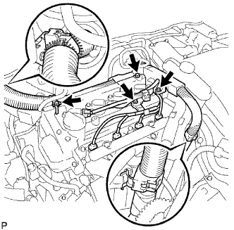 |
Install the wire harness and brake master cylinder reservoir cover with the 3 bolts.
Connect the fuel injector connector and ignition coil connector.
| 4. INSTALL RESERVOIR BRACKET |
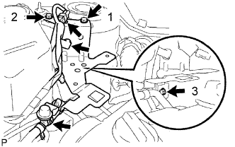 |
Temporarily install the reservoir bracket with the bolt labeled 1 in the illustration.
Tighten the 3 bolts to the specified torque in the sequence shown in the illustration.
Install the connector clamp.
Install the wire harness clamp.
Install the No. 2 fuel vapor feed hose to the hose clamp.
| 5. INSTALL BRAKE MASTER CYLINDER RESERVOIR SUB-ASSEMBLY |
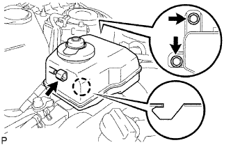 |
Install the reservoir with the 2 bolts.
Connect the switch connector.
| 6. INSTALL AIR CLEANER ASSEMBLY |
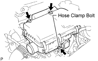 |
Install the air cleaner with the 2 bolts.
Tighten the hose clamp bolt.
Connect the No. 1 air cleaner inlet, and tighten the hose clamp bolt.
Connect the MAF meter connector.
| 7. INSTALL FRONT OUTER COWL TOP PANEL SUB-ASSEMBLY |
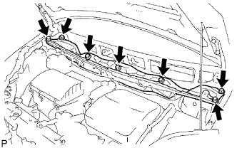 |
Install the panel with the 7 bolts.
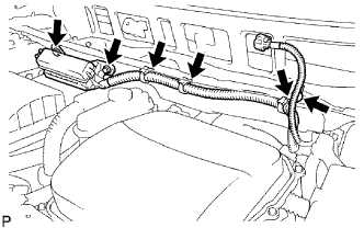 |
Connect the 4 wire harness clamps.
Install the No. 2 engine room relay block with the 2 bolts.
| 8. INSTALL WINDSHIELD WIPER MOTOR AND LINK |
Install the windshield wiper motor and link (Click here).
| 9. CONNECT CABLE TO NEGATIVE BATTERY TERMINAL |
| 10. INSPECT FOR FUEL LEAK |
Check that there are no leaks in the fuel system while fuel pressure is applied.
| 11. PERFORM INITIALIZATION |
Perform initialization (Click here).