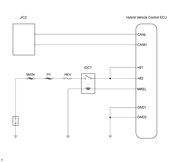
CAN COMMUNICATION SYSTEM > Hybrid Vehicle Control ECU Communication Stop Mode |
| Detection Item | Symptom | Trouble Area |
| HYBRID VEHICLE CONTROL ECU COMMUNICATION STOP MODE |
|
|
| 1.CHECK CAN BUS LINE FOR DISCONNECTION (HYBRID VEHICLE CONTROL ECU BRANCH WIRE) |
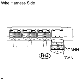 |
Disconnect the H14 hybrid vehicle control ECU connector.
Measure the resistance of the wire harness side connector.
| Tester Connection | Condition | Specified Condition |
| H14-8 (CANH) - H14-9 (CANL) | Power switch OFF | 54 to 69 Ω |
|
| ||||
| OK | |
 |
| 2.CHECK WIRE HARNESS (HYBRID VEHICLE CONTROL ECU - BATTERY AND BODY GROUND) |
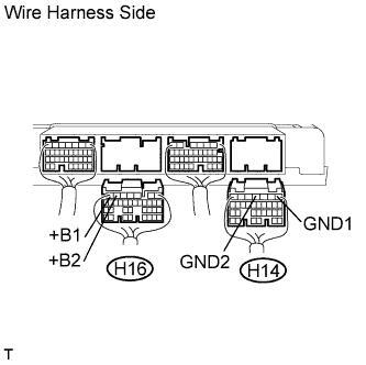 |
Disconnect the H16 hybrid vehicle control ECU connector.
Measure the resistance of the wire harness side connector.
| Tester Connection | Specified Condition |
| H14-1 (GND1) - Body ground | Below 1 Ω |
| H14-4 (GND2) - Body ground | Below 1 Ω |
Measure the voltage of the wire harness side connectors.
| Tester Connection | Condition | Specified Condition |
| H16-7 (+B1) - Body ground | Power switch ON (IG) | 10 to 14 V |
| H16-6 (+B2) - Body ground | Power switch ON (IG) | 10 to 14 V |
|
| ||||
| OK | ||
 | ||
| ||
