Home › BRAKE › BRAKE CONTROL › ELECTRONICALLY CONTROLLED BRAKE SYSTEM

DTC    C1377/43    Capacitor Malfunction

for Preparation Click here


DESCRIPTION

The brake control power supply (capacitor) provides auxiliary power for brake control when the auxiliary battery (12 V) voltage drops.

DTC No.
INF Code
DTC Detection Condition
Trouble Area
C1377/43
101
Brake control power supply assembly is deteriorated (indicates a need to replace).
Brake control power supply
C1377/43
102
Self-discharge (current leak) is excessive (internal malfunction).
Brake control power supply
C1377/43
103
Input voltage from the auxiliary battery (12 V) to the brake control power supply is 16.4 V or more for at least 10 sec.
Brake control power supply
C1377/43
105
Circuit inside the power back up unit (charge) is malfunctioning.
Brake control power supply
C1377/43
106
Circuit inside the power back up unit (back up output circuit) is malfunctioning.
Brake control power supply
C1377/43
108
Circuit inside the power back up unit (voltage monitor circuit) is malfunctioning.
Brake control power supply
C1377/43
109
Open circuit between auxiliary battery (12 V) and brake control power supply power input (+BC terminal).
  1. Harness and connector
  2. ABS MAIN3 fuse
C1377/43
110
When either condition below is met:
  1. Open or short circuit between auxiliary battery (12 V) and brake control power supply output 1 (OUT 1).
  2. Open or short circuit between auxiliary battery (12 V) and brake control power supply output 2 (OUT 2)
  1. Harness and connector
  2. ABS MAIN1 fuse
  3. ABS MAIN2 fuse

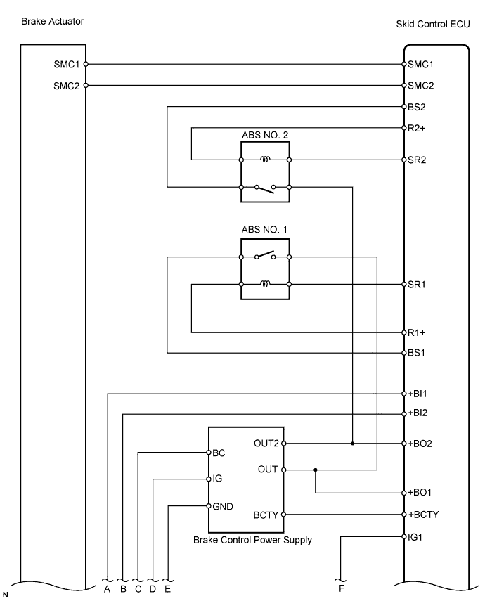
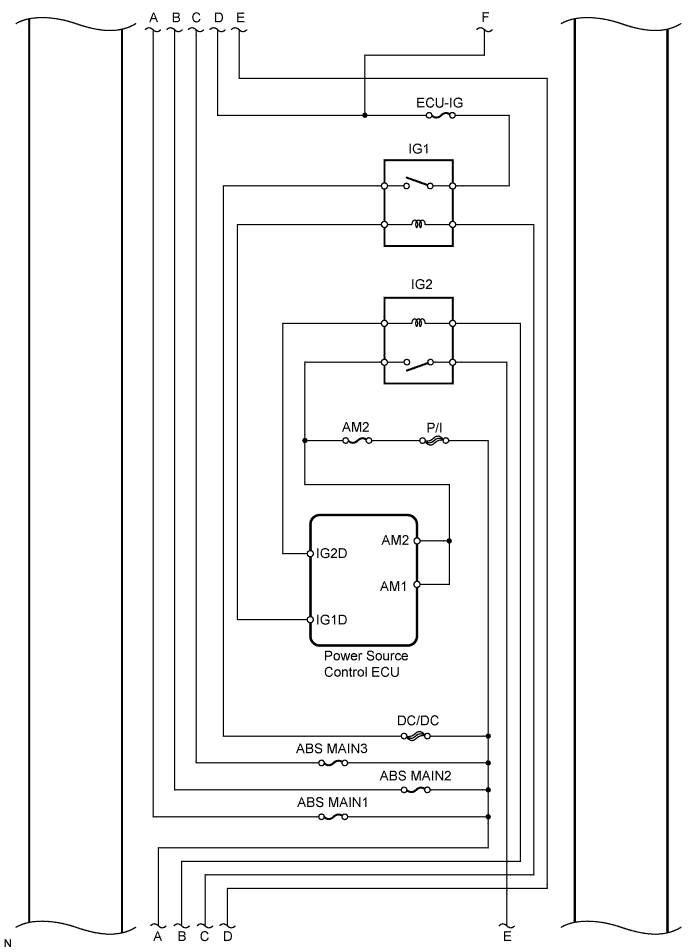
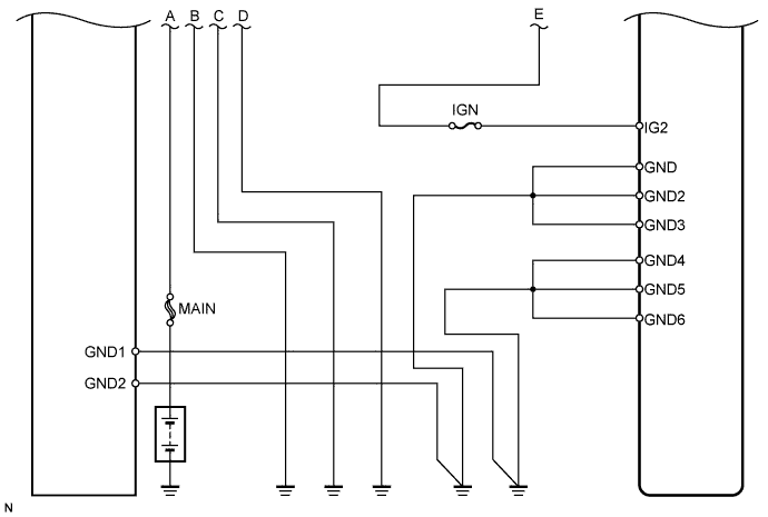
WIRING DIAGRAM


C126258E03


C153495E01


C126259E02


INSPECTION PROCEDURE

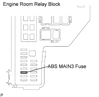
1.INSPECT FUSE (ABS MAIN3)


    F047764E01
  1. Remove the ABS MAIN3 fuse from the engine room relay block.

  1. Measure the resistance of the fuse.

    Standard resistance:
    Below 1 Ω


NG
CHECK FOR SHORT IN ALL HARNESS AND CONNECTOR CONNECTED TO FUSE AND REPLACE FUSE
OK


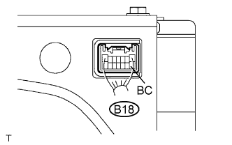
2.CHECK BRAKE CONTROL POWER SUPPLY (BC VOLTAGE)


    F047500E02
  1. Measure the voltage of the connector.

    HINT:
    Measure the voltage from behind the connector with the connector connected.

    Standard voltage:
    Tester Connection
    Specified Condition
    B18-8 (BC) - Body ground
    10 to 14 V


NG
REPAIR OR REPLACE HARNESS AND CONNECTOR
OK


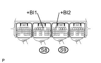
3.CHECK SKID CONTROL ECU (+BI1, +BI2 VOLTAGE)


    F047485E67
  1. Measure the voltage of the connectors.

    HINT:
    Measure the voltage from behind the connector with the connector connected to the skid control ECU.

    Standard voltage:
    Tester Connection
    Specified Condition
    S8-3 (+BI1) - Body ground
    10 to 14 V
    S9-5 (+BI2) - Body ground
    10 to 14 V


NG
REPAIR OR REPLACE HARNESS AND CONNECTOR
OK


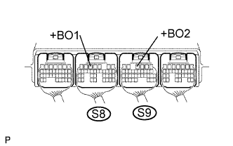
4.CHECK SKID CONTROL ECU (+BO1, +BO2 VOLTAGE)


    F047485E77
  1. Measure the voltage of the connectors.

    HINT:
    Measure the voltage from behind the connector with the connector connected to the skid control ECU.

    Standard voltage:
    Tester Connection
    Specified Condition
    S8-5 (+BO1) - Body ground
    10 to 14 V
    S9-4 (+BO2) - Body ground
    10 to 14 V


NG
REPAIR OR REPLACE HARNESS AND CONNECTOR
OK


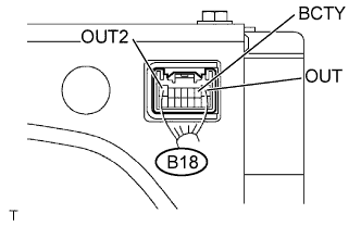
5.CHECK BRAKE CONTROL POWER SUPPLY (OUT, BCTY, OUT2 VOLTAGE)


    F047500E04
  1. Measure the voltage of the connector.

    HINT:
    Measure the voltage from behind the connector with the connector connected.

    Standard voltage:
    Tester Connection
    Condition
    Specified Condition
    B18-1 (OUT) - Body ground
    Power switch ON
    (READY)
    9 to 13 V
    B18-2 (BCTY) - Body ground
    Power switch ON
    (READY)
    9 to 13 V
    B18-7 (OUT2) - Body ground
    Power switch ON
    (READY)
    9 to 13 V


NG
REPLACE BRAKE CONTROL POWER SUPPLY
OK

REPAIR OR REPLACE HARNESS AND CONNECTOR