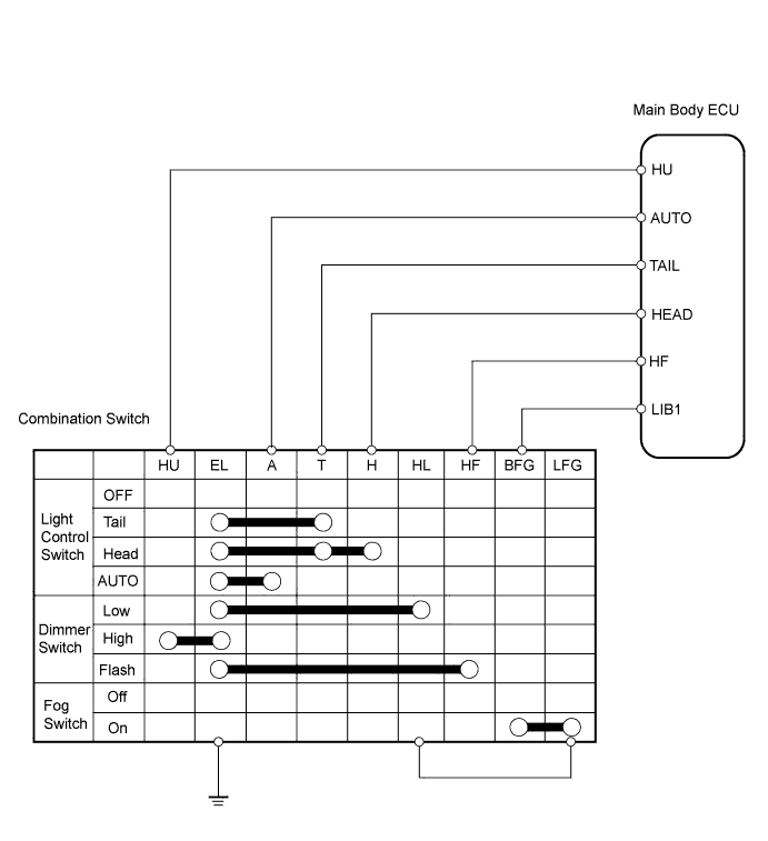
LIGHTING SYSTEM > Light Control Switch Circuit |
| 1.READ VALUE OF TECHSTREAM (COMBINATION SWITCH) |
Check the DATA LIST for the proper functioning of the combination switch.
| Item | Measurement Item / Display (Range) | Normal Condition | Diagnostic Note |
| Dimmer SW | Headlight dimmer switch signal / ON or OFF | ON: Headlight dimmer switch is in HIGH or FLASH position OFF: Headlight dimmer switch is in LOW position | - |
| Passing Light SW (Body) | Headlight dimmer switch signal / ON or OFF | ON: Headlight dimmer switch is in FLASH position OFF: Headlight dimmer switch is in except FLASH position | - |
| Auto Light SW | Auto light switch signal / ON or OFF | ON: Light control switch is in AUTO position OFF: Light control switch is in except AUTO position | - |
| Head Light SW (Head) | Headlight control switch signal / ON or OFF | ON: Light control switch is in HEAD position OFF: Light control switch is in except HEAD position | - |
| Head Light SW (Tail) | Taillight switch signal / ON or OFF | ON: Light control switch is in TAIL or HEAD position OFF: Light control switch is not in TAIL or HEAD position | - |
|
| ||||
| NG | |
 |
| 2.CHECK WIRE HARNESS (ECU - BODY GROUND) |
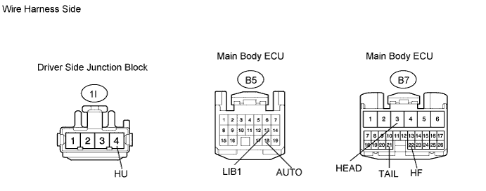
Disconnect the 1I junction block connector.
Disconnect the B5 and B7 ECU connectors.
Measure the resistance of the wire harness side connectors.
| Tester Connection | Condition | Specified Condition |
| 1I-4 (HU) - Body ground | Headlight dimmer switch LOW | 10 kΩ or higher |
| Headlight dimmer switch HIGH | Below 1 Ω | |
| B5-13 (LIB1) - Body ground | Fog switch OFF | 10 kΩ or higher |
| Fog switch AUTO | Below 1 Ω | |
| B5-18 (AUTO) - Body ground | Light control switch OFF | 10 kΩ or higher |
| Light control switch AUTO | Below 1 Ω | |
| B7-3 (HEAD) - Body ground | Light control switch OFF | 10 kΩ or higher |
| Light control switch HEAD | Below 1 Ω | |
| B7-21 (TAIL) - Body ground | Light control switch OFF | 10 kΩ or higher |
| Light control switch TAIL | Below 1 Ω | |
| B7-22 (HF) - Body ground | Headlight dimmer switch LOW | 10 kΩ or higher |
| Headlight dimmer switch FLASH | Below 1 Ω |
|
| ||||
| NG | |
|
| 3.INSPECT COMBINATION SWITCH |
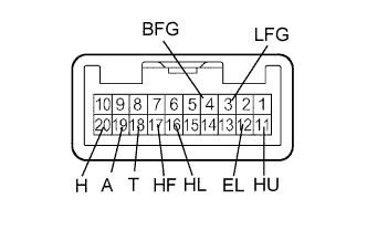 |
Inspect light control switch.
Measure the resistance of the switch.
| Tester Connection | Switch Condition | Specified Condition |
| 12 (EL) - 18 (T) 12 (EL) - 19 (A) 12 (EL) - 20 (H) | OFF | 10 kΩ or higher |
| 12 (EL) - 18 (T) | TAIL | Below 1 Ω |
| 12 (EL) - 18 (T) 12 (EL) - 20 (H) | HEAD | |
| 12 (EL) - 19 (A) | AUTO |
Inspect headlight dimmer switch.
Measure the resistance of the switch.
| Tester Connection | Switch Condition | Specified Condition |
| 11 (HU) - 12 (EL) 12 (EL) - 17 (HF) | FLASH | Below 1 Ω |
| 12 (EL) - 16 (HL) | Low | |
| 11 (HU) - 12 (EL) | High |
Inspect fog switch.
Measure the resistance of the switch.
| Tester Connection | Switch Condition | Specified Condition |
| 4 (BFG) - 3 (LFG) | ON | Below 1 Ω |
| OFF | 10 kΩ or higher |
|
| ||||
| OK | ||
 | ||
| ||
