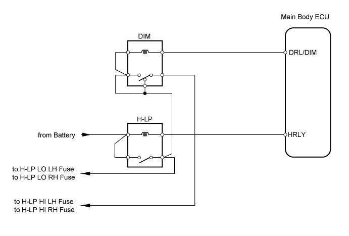
LIGHTING SYSTEM > Headlight Relay Circuit |
| 1.PERFORM ACTIVE TEST BY TECHSTREAM (HEADLIGHT) |
Select the ACTIVE TEST, use the Techstream to generate a control command, and then check that the headlight illuminates.
| Item | Test Details | Diagnostic Note |
| Headlight Relay | Turn headlight relay ON / OFF | - |
| Head Light Hi | Turn headlight dimmer relay (headlight dimmer switch in HIGH position) ON / OFF | - |
|
| ||||
| NG | |
 |
| 2.CHECK WIRE HARNESS (ECU - BODY GROUND) |
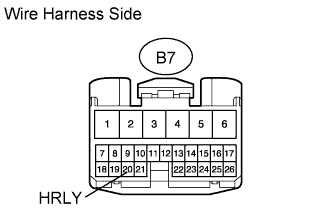 |
Disconnect the B7 ECU connector.
Using a service wire, connect B7-20 (HRLY) of the wire harness side and body ground.
|
| ||||
| OK | |
|
| 3.CHECK WIRE HARNESS (ECU - BODY GROUND) |
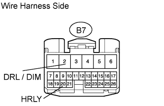 |
Disconnect the B7 ECU connector.
Using a service wire, connect B7-20 (HRLY) of the wire harness side and body ground.
Using a service wire, connect B7-2 (DRL/DIM) of the wire harness side and body ground.
|
| ||||
| OK | ||
 | ||
| ||
| 4.CHECK WIRE HARNESS (ECU - BATTERY) |
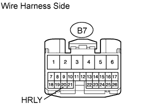 |
Disconnect the B7 ECU connector.
Measure the voltage of the wire harness side connector.
| Tester Connection | Specified Condition |
| B7-20 (HRLY) - Body ground | 10 to 14 V |
|
| ||||
| OK | ||
| ||
| ||
| 5.CHECK WIRE HARNESS (ECU - BATTERY) |
|
Disconnect the B7 ECU connector.
Using a service wire, connect B7-20 (HRLY) of the wire harness side and body ground.
Measure the voltage of the wire harness side connector.
| Tester Connection | Specified Condition |
| B7-2 (DRL/DIM) - Body ground | 10 to 14 V |
|
| ||||
| OK | ||
| ||
| ||

