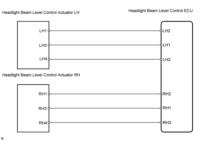
LIGHTING SYSTEM > Headlight Beam Level Control Actuator Circuit |
| 1.CHECK HEADLIGHT BEAM LEVEL CONTROL ECU |
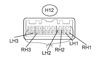 |
Measure the voltage of the wire harness side connector.
| Tester Connection | Condition | Specified Condition |
| H12-13 (RH1) - H12-22 (RH3) | Power switch ON (IG) | 10 to 14 V |
| H12-14 (LH1) - H12-23 (LH3) | ||
| H12-3 (RH2) - H12-22 (RH3) | With power switch ON (IG) and headlight on, change the vehicle height and maintain the height for more than 2 seconds | 10 to 12.6 V (Approx. 10 seconds) |
| H12-4 (LH2) - H12-23 (LH3) |
|
| ||||
| OK | |
 |
| 2.CHECK WIRE HARNESS (ECU - ACTUATOR) |
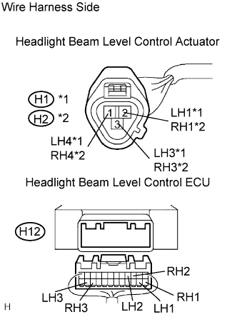 |
Disconnect the H1*1 or H2*2 actuator connector.
Disconnect the H12 ECU connector.
Measure the resistance of the wire harness side connector.
| Tester Connection | Specified Condition |
| H12-4 (LH2) - H1-2 (LH1) | Below 1 Ω |
| H12-14 (LH1) - H1-3 (LH3) | |
| H12-23 (LH3) - H1-1 (LH4) | |
| H12-4 (LH2) - Body ground | 10 kΩ or higher |
| H12-14 (LH1) - Body ground | |
| H12-23 (LH3) - Body ground |
| Tester Connection | Specified Condition |
| H12-3 (RH2) - H2-2 (RH1) | Below 1 Ω |
| H12-13 (RH1) - H2-3 (RH3) | |
| H12-22 (RH3) - H2-1 (RH4) | |
| H12-3 (RH2) - Body ground | 10 kΩ or higher |
| H12-13 (RH1) - Body ground | |
| H12-22 (RH3) - Body ground |
|
| ||||
| OK | ||
 | ||
| ||
