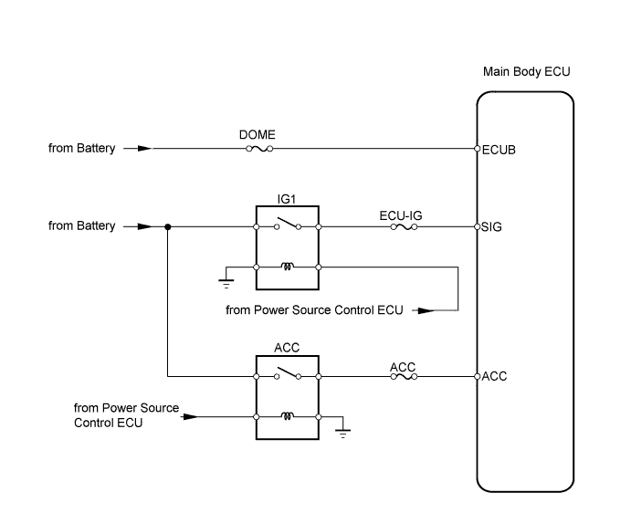
LIGHTING SYSTEM > Power Source Circuit |
| 1.READ VALUE OF TECHSTREAM (POWER SWITCH) |
Check the DATA LIST for proper functioning of the power switch.
| Item | Measurement Item / Display (Range) | Normal Condition | Diagnostic Note |
| ACC SW | ACC switch signal / ON or OFF | ON: Power switch ON (ACC) OFF: Power switch OFF | - |
| IG SW | IG switch signal / ON or OFF | ON: Power switch ON (IG) OFF: Power switch OFF | - |
|
| ||||
| NG | |
 |
| 2.CHECK DRIVER SIDE JUNCTION BLOCK (MAIN BODY ECU) |
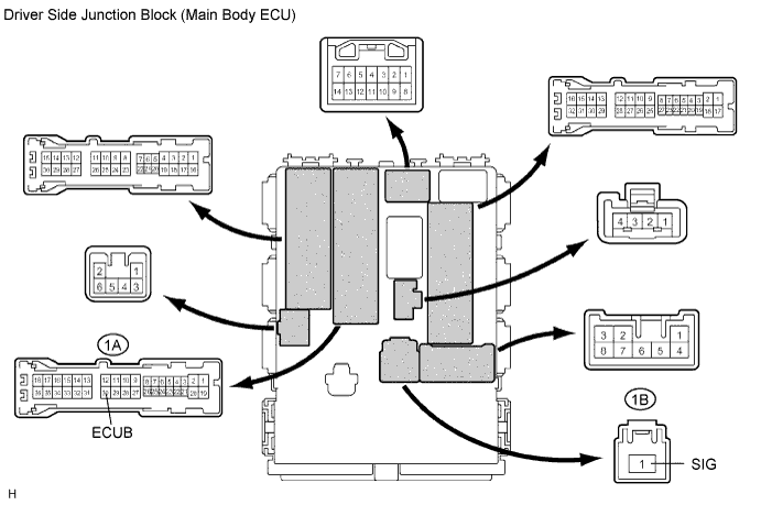
Measure the voltage of the connectors.
| Tester Connection | Specified Condition |
| 1A-30 (ECUB) - Body ground | 10 to 14 V |
| 1B-1 (SIG) - Body ground |
|
| ||||
| OK | |
|
| 3.CHECK DRIVER SIDE JUNCTION BLOCK (MAIN BODY ECU) |
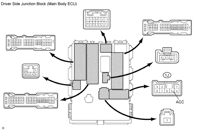
Measure the voltage of the connector.
| Tester Connection | Condition | Specified Condition |
| 1J-5 (ACC) - Body ground | Power switch ON (ACC) | 10 to 14 V |
|
| ||||
| NG | |
|
| 4.CHECK DRIVER SIDE JUNCTION BLOCK (MAIN BODY ECU) |
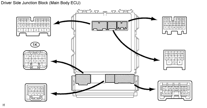
Measure the voltage of the connector.
| Tester Connection | Specified Condition |
| 1K-9 - Body ground | 10 to 14 V |
|
| ||||
| OK | ||
 | ||
| ||
