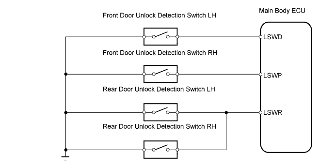
LIGHTING SYSTEM > Door LOCK Position Circuit |
| 1.READ VALUE OF TECHSTREAM (DOOR LOCK POSITION SWITCH) |
Check the DATA LIST for proper functioning of the door lock position switch.
| Item | Measurement item / Display (Range) | Normal Condition | Diagnostic Note |
| D-Door Lock Position SW | Driver's door lock position switch signal / ON or OFF | ON: Driver door lock is in unlock position OFF: Driver door lock is in lock position | - |
| Passenger Lock Pos SW | Front passenger's door lock position switch signal / ON or OFF | ON: Front passenger door lock is in unlock position OFF: Front passenger door lock is in lock position | - |
|
| ||||
| NG | |
 |
| 2.CHECK DRIVER SIDE JUNCTION BLOCK (MAIN BODY ECU) |
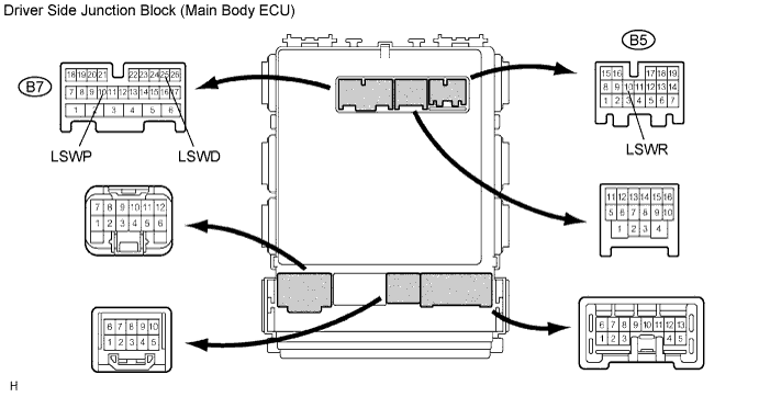
Measure the voltage of the connector.
| Tester Connection | Condition | Specified Condition |
| B7-25 (LSWD) - Body ground | Driver side door is locked | Below 1 V |
| Driver side door is unlocked | 10 to 14 V | |
| B7-10 (LSWP) - Body ground | Front passenger door is locked | Below 1 V |
| Front passenger door is unlocked | 10 to 14 V | |
| B5-10 (LSWR) - Body ground | Both rear doors are locked | Below 1 V |
| Both rear doors are unlocked | 10 to 14 V |
|
| ||||
| OK | ||
 | ||
| ||
