Home › BODY ELECTRICAL › LIGHTING › LIGHTING SYSTEM

LIGHTING SYSTEM > Taillight Relay Circuit

for Preparation Click here


DESCRIPTION

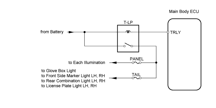
The main body ECU controls the T-LP relay when a signal is received from the combination switch.

WIRING DIAGRAM


I102410E01


INSPECTION PROCEDURE

1.PERFORM ACTIVE TEST BY TECHSTREAM (TAILLIGHT)
  1. Select the ACTIVE TEST, use the Techstream to generate a control command, and then check that the taillight illuminates.

    Main body ECU 
    Item
    Test Details
    Diagnostic Note
    Taillight Relay
    Turn taillight relay ON / OFF
    -

    OK:
    Each light comes on.


OK
PROCEED TO NEXT CIRCUIT INSPECTION SHOWN IN PROBLEM SYMPTOMS TABLE
NG


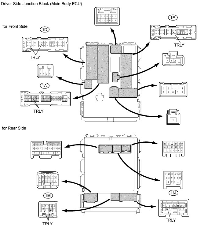
2.CHECK DRIVER SIDE JUNCTION BLOCK (MAIN BODY ECU)

I041126E07

  1. Measure the voltage of the connectors.

    Standard voltage:
    Tester Connection
    Condition
    Specified Condition
    1A-15 (TRLY) - Body ground
    Light control switch OFF
    Below 1 V
    Light control switch TAIL
    10 to 14 V
    1A-33 (TRLY) - Body ground
    Light control switch OFF
    Below 1 V
    Light control switch TAIL
    10 to 14 V
    1D-10 (TRLY) - Body ground
    Light control switch OFF
    Below 1 V
    Light control switch TAIL
    10 to 14 V
    1D-29 (TRLY) - Body ground
    Light control switch OFF
    Below 1 V
    Light control switch TAIL
    10 to 14 V
    1E-10 (TRLY) - Body ground
    Light control switch OFF
    Below 1 V
    Light control switch TAIL
    10 to 14 V
    1M-6 (TRLY) - Body ground
    Light control switch OFF
    Below 1 V
    Light control switch TAIL
    10 to 14 V
    1M-8 (TRLY) - Body ground
    Light control switch OFF
    Below 1 V
    Light control switch TAIL
    10 to 14 V
    1M-9 (TRLY) - Body ground
    Light control switch OFF
    Below 1 V
    Light control switch TAIL
    10 to 14 V
    1N-7 (TRLY) - Body ground
    Light control switch OFF
    Below 1 V
    Light control switch TAIL
    10 to 14 V


OK
REPAIR OR REPLACE HARNESS AND CONNECTOR (EACH TAILLIGHT CIRCUIT)
NG


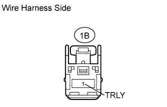
3.CHECK WIRE HARNESS (ECU - BATTERY)
I102539E01
  1. Disconnect the 1B junction block connector.

  1. Measure the voltage of the wire harness side connector.

    Standard voltage:
    Tester Connection
    Specified Condition
    1B-1 (TRLY) - Body ground
    10 to 14 V


NG
REPAIR OR REPLACE HARNESS AND CONNECTOR
OK

PROCEED TO NEXT CIRCUIT INSPECTION SHOWN IN PROBLEM SYMPTOMS TABLE