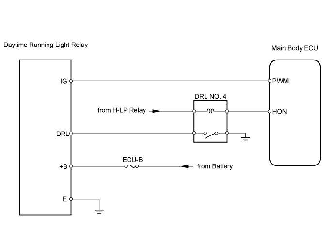
LIGHTING SYSTEM > Daytime Running Light Relay Circuit |
| 1.PERFORM ACTIVE TEST BY TECHSTREAM (DAYTIME RUNNING LIGHT RELAY) |
Select the ACTIVE TEST, use the Techstream to generate a control command, and then check that the headlight illuminates.
| Item | Test Details | Diagnostic Note |
| Relay of DRL | (Test Details) Turn daytime running light relay ON / OFF (Vehicle Condition) Power switch ON (IG), engine is stopped and light control switch is in off | - |
|
| ||||
| NG | |
 |
| 2.CHECK DAYTIME RUNNING LIGHT RELAY |
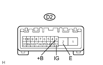 |
Measure the voltage of the relay connector.
| Tester Connection | Condition | Specified Condition |
| D2-2 (E) - D2-3 (+B) | Always | 10 to 14 V |
| D2-2 (E) - D2-12 (IG) | Engine is running and parking brake is released |
|
| ||||
| OK | |
|
| 3.CHECK WIRE HARNESS (ECU - BATTERY) |
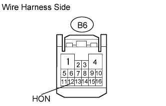 |
Disconnect the B6 ECU connector.
Measure the voltage of the wire harness side connector.
| Tester Connection | Condition | Specified Condition |
| B6-12 (HON) - Body ground | Light control switch in HEAD | Below 1 V |
| Light control switch not in HEAD | 10 to 14 V |
|
| ||||
| OK | ||
 | ||
| ||
| 4.CHECK WIRE HARNESS (DAYTIME RUNNING LIGHT RELAY - BODY GROUND) |
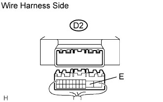 |
Disconnect the D2 relay connector.
Measure the resistance of the wire harness side connector.
| Tester Connection | Specified Condition |
| D2-2 (E) - Body ground | Below 1 Ω |
|
| ||||
| OK | |
|
| 5.CHECK WIRE HARNESS (DAYTIME RUNNING LIGHT RELAY - BATTERY) |
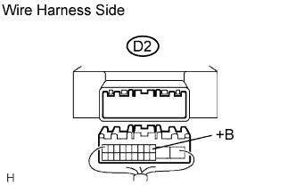 |
Disconnect the D2 relay connector.
Measure the voltage of the wire harness side connector.
| Tester Connection | Specified Condition |
| D2-3 (+B) - Body ground | 10 to 14 V |
|
| ||||
| OK | |
|
| 6.CHECK DRIVER SIDE JUNCTION BLOCK (MAIN BODY ECU) |
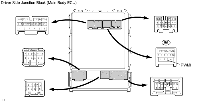
Measure the voltage of the connector.
| Tester Connection | Condition | Specified Condition |
| B6-3 (PWMI) - Body ground | Light control switch in HEAD | Below 1 V |
| Engine is running and parking brake is released | 10 to 14 V |
|
| ||||
| OK | ||
| ||
| ||

