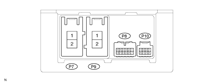
Symbols (Terminal No.)
| Wiring Color
| Terminal Description
| Condition
| Specified Condition
|
PIG (P7-1) - PGND (P7-2)
| W - W-B
| Power source
| Always
| 10 to 16 V
|
PGND (P7-2) - Body ground
| W-B - Body ground
| Power ground
| Always
| Below 1 Ω
|
M1 (P9-1) - PGND (P7-2)
| R - W-B
| Power steering motor signal
| With power switch ON (IG), turn the steering wheel to left
| Below 1 V
|
With power switch ON (IG), turn the steering wheel to right
| 10 to 16 V
|
M2 (P9-2) - PGND (P7-2)
| B - W-B
| Power steering motor signal
| With power switch ON (IG), turn the steering wheel to left
| 10 to 16 V
|
With power switch ON (IG), turn the steering wheel to right
| Below 1 V
|
CANH (P8-1) - CANL (P8-7)
| B - W
| CAN communication line
| Power switch is OFF
| 54 to 69 Ω
|
SIL (P8-2) - PGND (P7-2)
| W - W-B
| Diagnosis communication signal
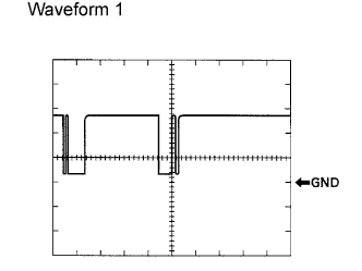
| Communication is established by connecting the Techstream (with CAN VIM) to the DLC3
| Pulse generation (see waveform 1)
|
IG (P8-6) - PGND (P7-2)
| B - W-B
| IG power source
| Power switch is ON (IG)
| 10 to 16 V
|
TRQ1 (P10-5) - PGND (P7-2)
| B - W-B
| Torque sensor signal
| With power switch ON (IG), turn the steering wheel to left and right
| 0.3 to 4.7 V
|
TRQV (P10-6) - PGND (P7-2)
| Y - W-B
| Torque sensor voltage source
| Power switch ON (IG)
| 7.5 to 8.5 V
|
TRQ2 (P10-7) - PGND (P7-2)
| R - W-B
| Torque sensor signal
| With power switch ON (IG), turn the steering wheel to left and right
| 0.3 to 4.7 V
|
TRQG (P10-8) - PGND (P7-2)
| W - W-B
| Torque sensor ground
| Always
| Below 1 Ω
|