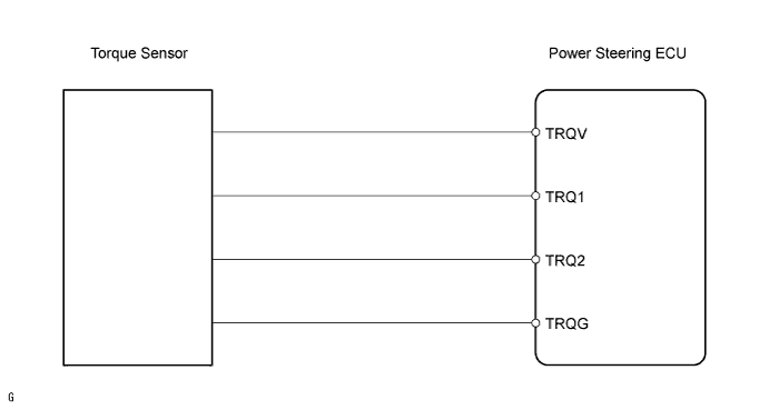
DTC C1511 Torque Sensor Circuit Malfunction |
DTC C1512 Torque Sensor Circuit Malfunction |
DTC C1513 Torque Sensor Circuit Malfunction |
DTC C1514 Torque Sensor Power Supply Abnormal |
DTC C1517 Torque Hold Abnormal |
| DTC No. | DTC Detection Condition | Trouble Area |
| C1511 | Torque sensor (TRQ1) signal error or stop |
|
| C1512 | Torque sensor (TRQ2) signal error or stop |
|
| C1513 | Deviation between torque sensors (TRQ1 and TRQ2) is out of specification |
|
| C1514 | Torque sensor power source voltage error |
|
| C1517 | Temporary control due to malfunction related to torque sensor continues for a long time |
|
| 1.READ VALUE OF TECHSTREAM (TORQUE SENSOR) |
Connect the Techstream (with CAN VIM) to the DLC3.
Turn the power switch ON (IG).
Turn the Techstream on.
Check the torque sensor output value. Enter the following menus: Chassis / EMPS / Data List.
| Tester Display | Measurement Item/Range | Normal Condition | Diagnostic Note |
| Torque Sensor 1 Output | Torque sensor 1 output value / min.: 0 V, max.: 5 V | 2.3 to 2.7 V | Steering wheel is not turned (without load) |
| 2.5 to 4.7 V | Turning steering wheel to right with vehicle stopped | ||
| 0.3 to 2.5 V | Turning steering wheel to left with vehicle stopped | ||
| Torque Sensor 2 Output | Torque sensor 2 output value / min.: 0 V, max.: 5 V | 2.3 to 2.7 V | Steering wheel is not turned (without load) |
| 2.5 to 4.7 V | Turning steering wheel to right with vehicle stopped | ||
| 0.3 to 2.5 V | Turning steering wheel to left with vehicle stopped |
Read the values of "Torque Sensor 1 Output" and "Torque Sensor 2 Output" on the Techstream display when the steering wheel is centered (without load).
Check the difference in the values of "Torque Sensor 1 Output" and "Torque Sensor 2 Output" when the steering wheel is centered (without load).
Read the value of the torque sensor on the Techstream display when the steering wheel is turned.
Turn the steering wheel from its center position to the right full lock position and read the values of "Torque Sensor 1 Output" and "Torque Sensor 2 Output" on the Techstream display.
Turn the steering wheel from its center position to the left full lock position and read the values of "Torque Sensor 1 Output" and "Torque Sensor 2 Output" on the Techstream display.
Check the difference in the values of "Torque Sensor 1 Output" and "Torque Sensor 2 Output".
|
| ||||
| NG | |
 |
| 2.CHECK STEERING COLUMN ASSEMBLY (TORQUE SENSOR) |
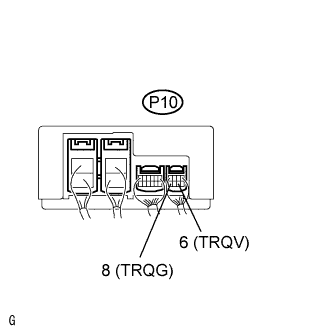 |
Measure the voltage of the ECU.
| Tester Connection | Condition | Specified Condition |
| P10-6 (TRQV) - P10-8 (TRQG) | Power switch is ON (IG) | 7.5 to 8.5 V |
|
| ||||
| NG | |
|
| 3.CHECK POWER STEERING ECU |
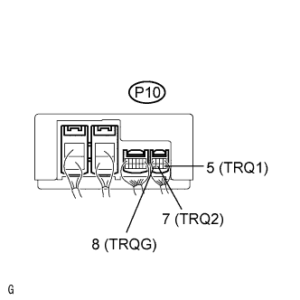 |
Measure the voltage of the ECU.
| Tester Connection | Condition | Specified Condition |
| P10-5 (TRQ1) - P10-8 (TRQG) | Power switch is ON (IG) Steering wheel center position | 2.3 to 2.7 |
| P10-7 (TRQ2) - P10-8 (TRQG) | Power switch is ON (IG) Steering wheel center position | 2.3 to 2.7 |
| P10-5 (TRQ1) - P10-8 (TRQG) | Power switch is ON (IG) Steering wheel turned to right | 2.5 to 4.7 |
| P10-7 (TRQ2) - P10-8 (TRQG) | Power switch is ON (IG) Steering wheel turned to right | 2.5 to 4.7 |
| P10-5 (TRQ1) - P10-8 (TRQG) | Power switch is ON (IG) Steering wheel turned to left | 0.3 to 2.5 V |
| P10-7 (TRQ2) - P10-8 (TRQG) | Power switch is ON (IG) Steering wheel turned to left | 0.3 to 2.5 V |
|
| ||||
| NG | ||
 | ||
| ||
