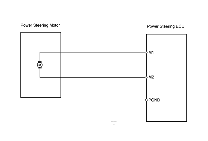
DTC C1524 Motor Circuit Malfunction |
| DTC No. | DTC Detection Condition | Trouble Area |
| C1524 | Voltage error between motor terminals |
|
| 1.CHECK POWER STEERING ECU |
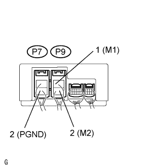 |
Turn the power switch ON (IG).
Measure the voltage of the ECU.
| Tester Connection | Condition | Specified Condition |
| P9-1 (M1) - P7-2 (PGND) | The steering wheel is turned to the left. | Below 1 V |
| P9-1 (M1) - P7-2 (PGND) | The steering wheel is turned to the right. | 10 to 16 V |
| P9-2 (M2) - P7-2 (PGND) | The steering wheel is turned to the left. | 10 to 16 V |
| P9-2 (M2) - P7-2 (PGND) | The steering wheel is turned to the right. | Below 1 V |
|
| ||||
| OK | |
 |
| 2.CHECK POWER STEERING MOTOR |
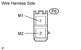 |
Turn the power switch OFF.
Disconnect the P9 power steering ECU connector.
Measure the resistance of the wire harness side connector.
| Tester Connection | Specified Condition |
| P9-1 (M1) - P9-2 (M2) | 0.04 to 0.1 Ω |
| P9-1 (M1) - Body ground | 10 kΩ or higher |
| P9-2 (M2) - Body ground | 10 kΩ or higher |
|
| ||||
| OK | ||
 | ||
| ||
