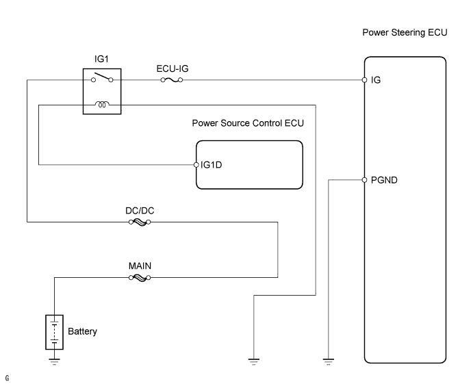
DTC C1551 IG Power Supply Voltage Malfunction |
| DTC No. | DTC Detection Condition | Trouble Area |
| C1551 | There is an open or short in the IG power source circuit with the power switch ON (IG). |
|
| 1.INSPECT FUSE (ECU-IG) |
Remove the ECU-IG fuse from the driver side junction block.
Measure the resistance of the fuse.
|
| ||||
| OK | |
 |
| 2.CHECK WIRE HARNESS (POWER STEERING ECU - BODY GROUND) |
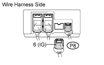 |
Disconnect the P8 power steering ECU connector.
Turn the power switch ON (IG).
Measure the voltage of the wire harness side connector.
| Tester Connection | Condition | Specified Condition |
| P8-6 (IG) - Body ground | Power switch is ON (IG) | 10 to 16 V |
|
| ||||
| OK | |
|
| 3.CHECK WIRE HARNESS (POWER STEERING ECU - BODY GROUND) |
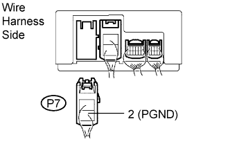 |
Turn the power switch OFF.
Disconnect the P7 power steering ECU connector.
Measure the resistance of the wire harness side connector.
| Tester Connection | Specified Condition |
| P7-2 (PGND) - Body ground | Below 1 Ω |
|
| ||||
| OK | ||
 | ||
| ||
