
SMART KEY SYSTEM > TERMINALS OF ECU |
| CHECK POWER SOURCE CONTROL ECU |
Disconnect the P6 ECU connector.
Measure the resistance and voltage of the wire harness side connector.
| Symbols (Terminal No.) | Wiring Color | Terminal Description | Condition | Specified Condition |
| AM1 (P6-33) - Body ground | R - Body ground | +B power supply | Always | 10 to 14 V |
| AM2 (P6-12) - Body ground | W - Body ground | +B power supply | Always | 10 to 14 V |
| CDSW (P6-25) - Body ground | L - Body ground | Key condition | No key in key slot | Below 1 Ω |
| CDSW (P6-25) - Body ground | L - Body ground | Key condition | Key inserted | 10 kΩ or higher |
| SSW1 (P6-14) - Body ground | B - Body ground | Power switch signal | Power switch pushed | Below 1 Ω |
| SSW1 (P6-14) - Body ground | B - Body ground | Power switch signal | Power switch not pushed | 10 kΩ or higher |
| SSW2 (P6-37) - Body ground | Y - Body ground | Power switch signal | Power switch pushed | Below 1 Ω |
| SSW2 (P6-37) - Body ground | Y - Body ground | Power switch signal | Power switch not pushed | 10 kΩ or higher |
| GND2 (P6-6) - Body ground | W-B - Body ground | Ground | Always | Below 1 Ω |
Reconnect the P6 ECU connector.
Measure the resistance and voltage of the connector.
| Symbols (Terminal No.) | Wiring Color | Terminal Description | Condition | Specified Condition |
| SOL1 (P6-3) - GND2 (P6-6) | P - W-B | Power switch signal | Brake pedal is not depressed, power switch ON (ACC) | 0 V |
| SOL1 (P6-3) - GND2 (P6-6) | P - W-B | Power switch signal | Brake pedal is not depressed, power switch ON (IG) | 10 to 14 V |
| SOL2 (P6-20) - GND2 (P6-6) | GR - W-B | Power switch signal | Always | Below 1 Ω |
| ACCD (P6-11) - GND2 (P6-6) | G - W-B | ACC signal | Power switch OFF | 0 V |
| ACCD (P6-11) - GND2 (P6-6) | G - W-B | ACC signal | Power switch ON (ACC) | 10 to 14 V |
| IG1D (P6-34) - GND2 (P6-6) | B - W-B | IG1 signal | Power switch ON (ACC) | 0 V |
| IG1D (P6-34) - GND2 (P6-6) | B - W-B | IG1 signal | Power switch ON (IG) | 10 to 14 V |
| IG2D (P6-35) - GND2 (P6-6) | V - W-B | IG2 signal | Power switch ON (ACC) | 0 V |
| IG2D (P6-35) - GND2 (P6-6) | V - W-B | IG2 signal | Power switch ON (IG) | 10 to 14 V |
| STP (P6-1) - GND2 (P6-6) | L - W-B | Stop light signal | Brake pedal depressed | 10 to 14 V |
| STP (P6-1) - GND2 (P6-6) | L - W-B | Stop light signal | Brake pedal released | 0 V |
| CHECK TRANSPONDER KEY ECU |
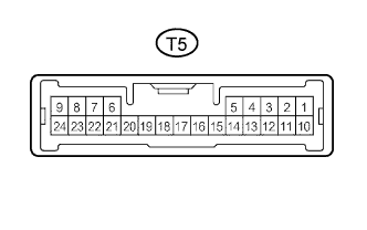
Disconnect the T5 ECU connector.
Measure the resistance and voltage of the wire harness side connector.
| Symbols (Terminal No.) | Wiring Color | Terminal Description | Condition | Specified Condition |
| CPUB (T5-3) - GND (T5-22) | L - W-B | Battery | Always | 10 to 14 V |
| IG (T5-4) - GND (T5-22) | O - W-B | Power switch (IG) | Power switch OFF | 0 V |
| IG (T5-4) - GND (T5-22) | O - W-B | Power switch (IG) | Power switch ON (IG) | 10 to 14 V |
| ACC (T5-12) - GND (T5-22) | P - W-B | Power switch (ACC) | Power switch OFF | 0 V |
| ACC (T5-12) - GND (T5-22) | P - W-B | Power switch (ACC) | Power switch ON (ACC) | 10 to 14 V |
| CUWS (T5-5) - GND (T5-22) | B - W-B | Halfway switch | No key in key slot | 10 kΩ or higher |
| CUWS (T5-5) - GND (T5-22) | B - W-B | Halfway switch | Key inserted | Below 1 Ω |
| AGND (T5-7) - GND (T5-22) | P - W-B | Ground | Always | Below 1 Ω |
| GND (T5-22) - Body ground | W-B - Body ground | Ground | Always | Below 1 Ω |
Reconnect the T5 ECU connector.
Measure the voltage of the connector.
| Symbols (Terminal No.) | Wiring Color | Terminal Description | Condition | Specified Condition |
| CUWS (T5-5) - GND (T5-22) | B - W-B | Halfway switch | No key in key slot | 10 to 14 V |
| CUWS (T5-5) - GND (T5-22) | B - W-B | Halfway switch | Key inserted | Below 1 V |
| VC5 (T5-20) - GND (T5-22) | Y - W-B | Power source | No key in key slot | 0 V |
| VC5 (T5-20) - GND (T5-22) | Y - W-B | Power source | Key inserted | 4.6 to 5.4 V |
| CHECK HYBRID VEHICLE CONTROL ECU |
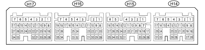
Disconnect the H14, H15, H16 and H17 ECU connectors.
Measure the resistance and voltage of the connectors.
| Symbols (Terminal No.) | Wiring Color | Terminal Description | Condition | Specified Condition |
| ST2 (H14-5) - GND1 (H14-1) | Y - W-B | Ignition start control signal input | Power switch ON (READY) | 10 to 14 V |
| IGSW (H14-7) - GND1 (H14-1) | O - W-B | Ignition ready control signal input | Power switch ON (IG) | 10 to 14 V |
| BATT (H15-6) - GND1 (H14-1) | Y - W-B | Battery | Always | 10 to 14 V |
| +B1 (H16-7) - GND1 (H14-1) | L - W-B | Ignition power supply | Power switch ON (IG) | 10 to 14 V |
| +B2 (H16-6) - GND1 (H14-1) | L - W-B | Ignition power supply | Power switch ON (IG) | 10 to 14 V |
| GND1 (H14-1) - Body ground | W-B - Body ground | Ground | Always | Below 1 Ω |
| GND2 (H14-4) - Body ground | W-B - Body ground | Ground | Always | Below 1 Ω |
| CHECK TRANSMISSION CONTROL ECU |

Disconnect the T4 ECU connector.
Measure the resistance and voltage of the wire harness side connector.
| Symbols (Terminal No.) | Wiring Color | Terminal Description | Condition | Specified Condition |
| BATT (T4-13) - Body ground | L - Body ground | +B power supply | Always | 10 to 14 V |
| +B (T4-1) - Body ground | L - Body ground | Ignition power supply | Power switch ON (IG) | 10 to 14 V |
| E1 (T4-15) - Body ground | W-B - Body ground | Ground | Always | Below 1 Ω |
| E01 (T4-3) - Body ground | W-B - Body ground | Ground | Always | Below 1 Ω |
| E02 (T4-2) - Body ground | W-B - Body ground | Ground | Always | Below 1 Ω |