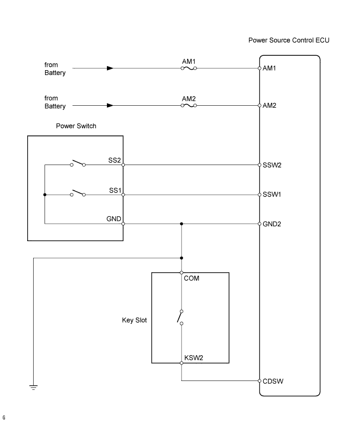
SMART KEY SYSTEM > Power Source Mode does not Change to ON (IG and ACC) |
| 1.INSPECT FUSE (AM1, AM2) |
Remove the AM1 fuse from the driver side junction block.
Remove the AM2 fuse from the engine room junction block.
Measure the resistance of the fuses.
|
| ||||
| OK | |
 |
| 2.CHECK WIRE HARNESS (POWER SOURCE CONTROL ECU - BATTERY AND BODY GROUND) |
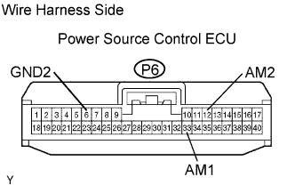 |
Disconnect the P6 ECU connector.
Measure the resistance and voltage of the wire harness side connector.
| Tester Connection | Specified Condition |
| P6-6 (GND2) - Body ground | Below 1 Ω |
| Tester Connection | Specified Condition |
| P6-33 (AM1) - Body ground | 10 to 14 V |
| P6-12 (AM2) - Body ground | 10 to 14 V |
|
| ||||
| OK | |
|
| 3.CHECK FOR DTC (POWER SOURCE CONTROL ECU) |
Check for DTCs of the power source control ECU.
|
| ||||
| OK | |
|
| 4.CHECK FOR DTC (TRANSPONDER KEY ECU) |
Check for DTCs of the transponder key ECU.
| Result | Proceed to |
| DTCs of transponder key ECU are not output | A |
| DTCs of transponder key ECU are output (w/ smart key system (for door lock)) | B |
| DTCs of transponder key ECU are output (w/o smart key system (for door lock)) | C |
|
| ||||
|
| ||||
| A | |
|
| 5.READ VALUE OF DATA LIST (STEERING UNLOCK SWITCH) |
Connect Techstream to the DLC3.
Press Techstream main switch ON.
Read the DATA LIST according to the displays on the tester.
| Tester Display | Measurement Item/Range | Normal Condition | Diagnostic Note |
| Steering Unlock Switch | Steering unlock switch / ON or OFF | ON: Key is in key slot OFF: No key is in key slot | - |
|
| ||||
| NG | |
|
| 6.CHECK WIRE HARNESS (KEY SLOT - POWER SOURCE CONTROL ECU AND BODY GROUND) |
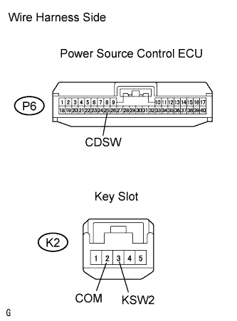 |
Disconnect the K2 key slot connector.
Disconnect the P6 ECU connector.
Measure the resistance of the wire harness side connectors.
| Tester Connection | Specified Condition |
| K2-3 (KSW2) - P6-25 (CDSW) | Below 1 Ω |
| K2-2 (COM) - Body ground | Below 1 Ω |
| K2-3 (KSW2) or P6-25 (CDSW) - Body ground | 10 kΩ or higher |
|
| ||||
| OK | |
|
| 7.INSPECT KEY SLOT |
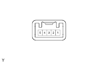 |
Remove the key slot.
Measure the resistance of the key slot.
| Tester Connection | Condition | Specified Condition |
| K2-3 (KSW2) - K2-2 (COM) | Key is in key slot | 10 kΩ or higher |
|
| ||||
| OK | ||
 | ||
| ||
| 8.READ VALUE OF DATA LIST (START SWITCH 1 and 2) |
Connect Techstream to the DLC3.
Press Techstream main switch ON.
Read the DATA LIST according to the displays on the tester.
| Tester Display | Measurement Item/Display | Normal Condition | Diagnostic Note |
| Start Switch1 | Start switch 1 / ON or OFF | ON: Power switch ON (IG) (push power switch) OFF: Power switch OFF (release power switch) | - |
| Start Switch2 | Start switch 2 / ON or OFF | ON: Power switch ON (IG) (push power switch) OFF: Power switch OFF (release power switch) | - |
|
| ||||
| NG | |
|
| 9.CHECK WIRE HARNESS (POWER SWITCH - POWER SOURCE CONTROL ECU AND BODY GROUND) |
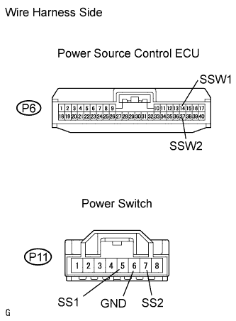 |
Disconnect the P11 power switch connector.
Disconnect the P6 ECU connector.
Measure the resistance of the wire harness side connectors.
| Tester Connection | Specified Condition |
| 5 (SS1) - 14 (SSW1) | Below 1 Ω |
| 7 (SS2) - 37 (SSW2) | Below 1 Ω |
| 6 (GND) - Body ground | Below 1 Ω |
| 5 (SS1) or 14 (SSW1) - Body ground | 10 kΩ or higher |
| 7 (SS2) or 37 (SSW2) - Body ground | 10 kΩ or higher |
|
| ||||
| OK | |
|
| 10.INSPECT POWER SWITCH |
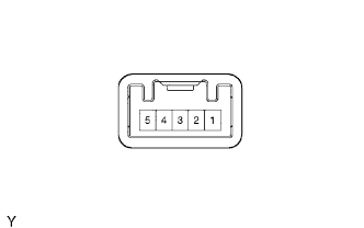 |
Remove the power switch.
Measure the resistance of the switch.
| Tester Connection | Switch Condition | Specified Condition |
| 7 (SS2) - 6 (GND) | Pushed | Below 1 Ω |
| 5 (SS1) - 6 (GND) | Pushed | Below 1 Ω |
| 7 (SS2) - 6 (GND) | Released | 10 kΩ or higher |
| 5 (SS1) - -6 (GND) | Released | 10 kΩ or higher |
|
| ||||
| OK | ||
| ||
| ||

