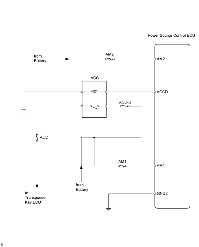
SMART KEY SYSTEM > Power Source Mode does not Change to ON (ACC) |
| 1.INSPECT FUSE (AM1, AM2) |
Remove the AM1 fuse from the driver side junction block.
Remove the AM2 fuse from the engine room junction block.
Measure the resistance of the fuses.
|
| ||||
| OK | |
 |
| 2.CHECK WIRE HARNESS (POWER SOURCE CONTROL ECU - BATTERY AND BODY GROUND) |
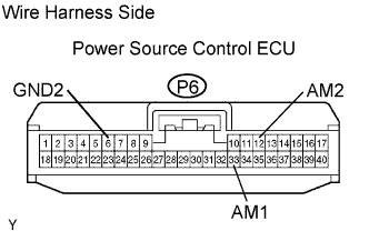 |
Disconnect the P6 ECU connector.
Measure the resistance and voltage of the wire harness side connector.
| Tester Connection | Specified Condition |
| P6-6 (GND2) - Body ground | Below 1 Ω |
| Tester Connection | Specified Condition |
| P6-33 (AM1) - Body ground | 10 to 14 V |
| P6-12 (AM2) - Body ground | 10 to 14 V |
|
| ||||
| OK | |
|
| 3.CHECK FOR DTC |
Check for DTCs of the power source control ECU.
|
| ||||
| OK | |
|
| 4.INSPECT ACC RELAY |
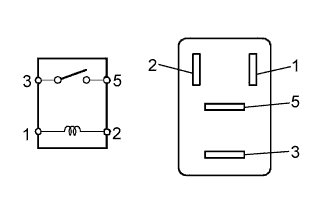 |
Remove the ACC relay.
Measure the resistance of the relay.
| Tester Connection | Specified Condition |
| 3 - 5 | 10 kΩ or higher |
| 3 - 5 | Below 1 Ω (when battery voltage is applied to terminals 1 and 2) |
|
| ||||
| OK | |
|
| 5.CHECK WIRE HARNESS (ACC RELAY - POWER SOURCE CONTROL ECU AND BODY GROUND) |
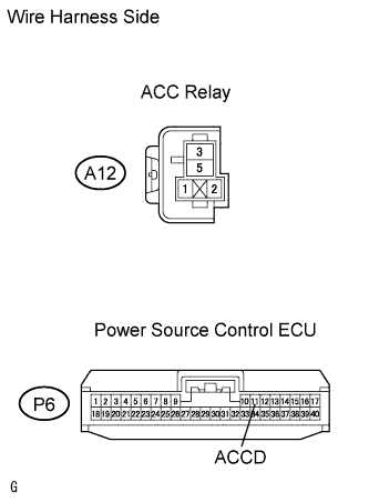 |
Remove the ACC relay.
Disconnect the P6 ECU connector.
Measure the resistance of the wire harness side connectors.
| Tester Connection | Specified Condition |
| A12-1 - P6-11 (ACCD) | Below 1 Ω |
| A12-2 - Body ground | Below 1 Ω |
| A12-1 - Body ground | 10 kΩ or higher |
|
| ||||
| OK | |
|
| 6.CHECK POWER SOURCE CONTROL ECU (ACCD VOLTAGE) |
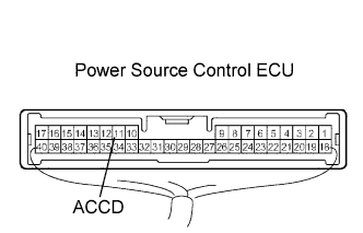 |
Measure the voltage of the connector.
| Tester Connection | Condition | Specified Condition |
| P6-11 (ACCD) - Body ground | Power switch ON (ACC) | 10 to 14 V |
| P6-11 (ACCD) - Body ground | Power switch OFF | Below 1 V |
|
| ||||
| OK | |
|
| 7.CHECK OPERATION OF POWER SOURCE CONTROL ECU |
After replacing the power source control ECU with a normally functioning ECU, check that the power switch can be set to ON (ACC).
| Result | Proceed to |
| Power switch can be set to ON (ACC) | A |
| Power switch cannot be set to ON (ACC) (w/ smart key system (for door lock)) | B |
| Power switch cannot be set to ON (ACC) (w/o smart key system (for door lock)) | C |
|
| ||||
|
| ||||
| A | ||
 | ||
| ||
