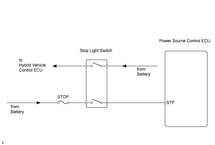
SMART KEY SYSTEM > Power Source Mode does not Change to ON (READY) |
| 1.BASIC INSPECTION |
Check that the P position switch is ON.
Turn the power switch ON (READY) and check that the hybrid control system starts normally. Make sure the brake pedal is depressed at this time.
|
| ||||
| NG | |
 |
| 2.CHECK OPERATION OF POWER SWITCH |
Check that the power mode can be changed by pushing the power switch.
|
| ||||
| OK | |
|
| 3.CHECK FOR DTC |
Check for DTCs of the power source control ECU.
|
| ||||
| OK | |
|
| 4.READ VALUE OF DATA LIST (STOP LIGHT SWITCH 1 and 2) |
Connect Techstream to the DLC3.
Turn the power switch ON (IG) and push Techstream main switch ON.
Read the DATA LIST according to the display on the tester.
| Tester Display | Measurement Item/Range | Normal Condition | Diagnostic Note |
| Stop Light Switch1 | Stop light switch 1 / ON or OFF | ON: Brake pedal depressed OFF: Brake pedal released | - |
| Stop Light Switch2 | Stop light switch 2 / ON or OFF | ON: Brake pedal depressed OFF: Brake pedal released | - |
|
| ||||
| NG | |
|
| 5.CHECK POWER SOURCE CONTROL ECU (STP VOLTAGE) |
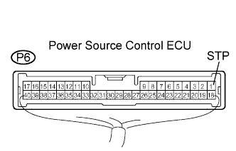 |
Measure the voltage when the brake pedal is operated.
| Tester Connection | Condition | Specified Condition |
| P6-1 (STP) - Body ground | Brake pedal released | 10 to 14 V |
| P6-1 (STP) - Body ground | Brake pedal depressed | Below 1 V |
|
| ||||
| NG | |
|
| 6.INSPECT STOP LIGHT SWITCH ASSEMBLY |
Remove the stop light switch.

Measure the resistance according to the value(s) in the table below.
| Tester Connection | Condition | Specified Condition |
| 1 - 2 | Switch pin not pushed | Below 1 Ω |
| 3 - 4 | Switch pin not pushed | 10 kΩ or higher |
| 1 - 2 | Switch pin pushed | 10 kΩ or higher |
| 3 - 4 | Switch pin pushed | Below 1 Ω |
|
| ||||
| OK | |
|
| 7.CHECK WIRE HARNESS (STOP LIGHT SWITCH - POWER SOURCE CONTROL ECU AND BATTERY) |
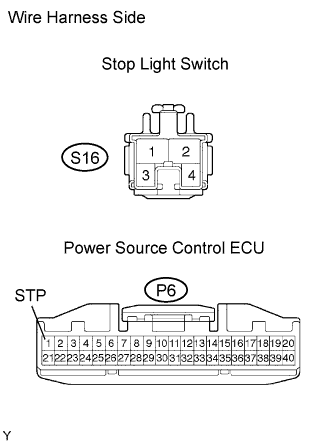 |
Disconnect the S16 switch connector.
Disconnect the P6 ECU connector.
Measure the resistance and voltage of the wire harness side connectors.
| Tester Connection | Specified Condition |
| S16-1 - P6-1 (STP) | Below 1 Ω |
| Tester Connection | Specified Condition |
| S16-2 - Body ground | 10 to 14 V |
|
| ||||
| OK | ||
 | ||
| ||
| 8.CHECK FOR DTC |
Check for DTCs of the hybrid vehicle control ECU.
|
| ||||
| OK | ||
| ||
| ||

