ELECTRONIC SHIFT LEVER SYSTEM > DIAGNOSIS SYSTEM |
| DESCRIPTION |
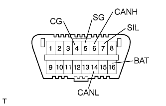
Electronic shift lever system data and the Diagnostic Trouble Codes (DTCs) can be read in the Data Link Connector 3 (DLC3) of the vehicle. When the system seems to be malfunctioning, use the Techstream to check for malfunctions and perform repairs.
| CHECK DLC3 |
|
| Terminal No. (Symbols) | Terminal Description | Condition | Specified Condition |
| 7 (SIL) - 5 (SG) | Bus "+" line | During transmission | Pulse generation |
| 4 (CG) - Body ground | Chassis ground | Always | Below 1 Ω |
| 5 (SG) - Body ground | Signal ground | Always | Below 1 Ω |
| 16 (BAT) - Body ground | Battery positive | Always | 11 to 14 V |
| 6 (CANH) - 14 (CANL) | HIGH-level CAN bus line | Power Switch OFF* | 54 to 69 Ω |
| 6 (CANH) - Battery positive (+) | HIGH-level CAN bus line | Power Switch OFF* | 6 kΩ or higher |
| 6 (CANH) - 4 (CG) | HIGH-level CAN bus line | Power Switch OFF* | 200 Ω or higher |
| 14 (CANL) - Battery positive (+) | LOW-level CAN bus line | Power Switch OFF* | 6 kΩ or higher |
| 14 (CANL) - 4 (CG) | LOW-level CAN bus line | Power Switch OFF* | 200 Ω or higher |