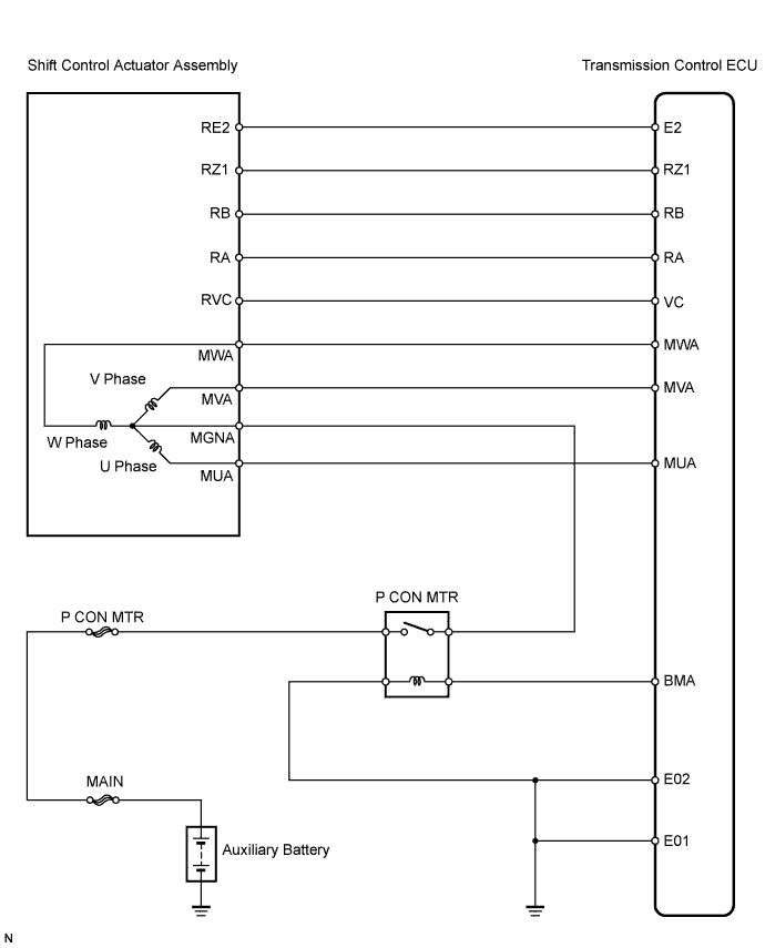
DTC C2300 ACT System Malfunction |
| DTC No. | DTC Detection Condition | Trouble Area |
| C2300 | When both conditions below are met:
|
|
| 1.CHECK OTHER DTC OUTPUT (BESIDES DTC C2300) |
Connect the Techstream to the DLC3.
Turn the power switch ON (IG).
Turn the Techstream on.
Read the DTCs.
| Display (DTC output) | Proceed to |
| No output | A |
| C2304, C2305, C2306 and C2318 | B |
|
| ||||
| A | |
 |
| 2.CHECK TRANSMISSION CONTROL ECU (VC, RA, RB, RZ1 VOLTAGE) |
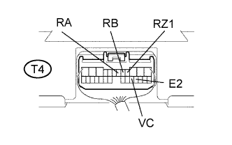 |
Measure the voltage of the ECU connector.
| Tester Connection | Condition | Specified Condition |
| T4-4 (RZ1) - T4-16 (E2) | Power switch ON (IG) | 4 to 5.5 V |
| T4-5 (RB) - T4-16 (E2) | Power switch ON (IG) | 4 to 5.5 V |
| T4-6 (RA) - T4-16 (E2) | Power switch ON (IG) | 4 to 5.5 V |
| T4-17 (VC) - T4-16 (E2) | Power switch ON (IG) | 4 to 5.5 V |
| Result | Proceed to |
| OK | A |
| NG | B |
|
| ||||
| B | |
|
| 3.CHECK WIRE HARNESS (TRANSMISSION CONTROL ECU - SHIFT CONTROL ACTUATOR) |
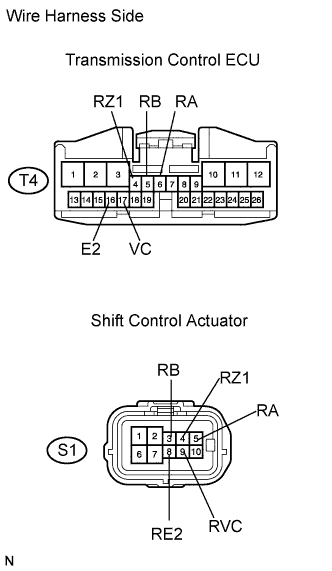 |
Disconnect the T4 ECU connector.
Disconnect the S1 actuator connector.
Measure the resistance of the wire harness side connectors.
| Tester Connection | Specified Condition |
| T4-17 (VC) - S1-9 (RVC) | Below 1 Ω |
| T4-5 (RB) - S1-3 (RB) | Below 1 Ω |
| T4-6 (RA) - S1-5 (RA) | Below 1 Ω |
| T4-4 (RZ1) - S1-4 (RZ1) | Below 1 Ω |
| T4-16 (E2) - S1-8 (RE2) | Below 1 Ω |
| T4-4 (RZ1) - Body ground | 10 kΩ or higher |
| T4-5 (RB) - Body ground | 10 kΩ or higher |
| T4-6 (RA) - Body ground | 10 kΩ or higher |
| T4-17 (VC) - Body ground | 10 kΩ or higher |
|
| ||||
| OK | |
|
| 4.CHECK WIRE HARNESS (TRANSMISSION CONTROL ECU - BODY GROUND) |
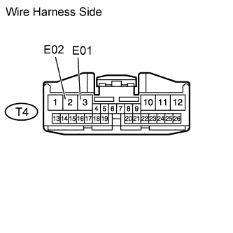 |
Disconnect the T4 ECU connector.
Measure the resistance of the wire harness side connector.
| Tester Connection (Symbols) | Specified Condition |
| T4-2 (E02) - Body ground | Below 1 Ω |
| T4-3 (E01) - Body ground | Below 1 Ω |
|
| ||||
| NG | ||
 | ||
| ||
| 5.CHECK WIRE HARNESS (SHIFT CONTROL ACTUATOR - BATTERY) |
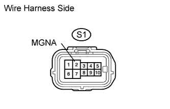 |
Disconnect the S1 actuator connector.
Measure the voltage of the wire harness side connector.
| Tester Connection | Condition | Specified Condition |
| S1-2 (MGNA) - Body ground | Power switch ON (IG) | 9 to 14 V |
|
| ||||
| OK | |
|
| 6.READ VALUE OF TECHSTREAM (U, V, W VOLTAGE) |
Check the Data List for proper functioning of the shift control actuator.
| Tester Display | Measurement Item / Range | Normal Condition | Diagnostic Note |
| U Phase Voltage Value | U phase voltage value / min: 0 V, max: 20 V | Actual U phase voltage 9 to 14 V | - |
| V Phase Voltage Value | V phase voltage value / min: 0 V, max: 20 V | Actual V phase voltage 9 to 14 V | - |
| W Phase Voltage Value | W phase voltage value / min: 0 V, max: 20 V | Actual W phase voltage 9 to 14 V | - |
|
| ||||
| OK | ||
| ||
| ||
| 7.INSPECT FUSE (P CON MTR) |
Remove the P CON MTR H-fuse from the engine room relay block.
Measure the resistance of the H-fuse.
|
| ||||
| OK | |
|
| 8.INSPECT TRANSAXLE PARKING LOCK CONTROL RELAY (Marking: P CON) |
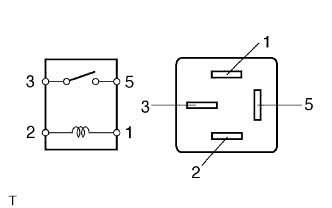 |
Remove the P CON MTR relay from the engine room relay block.
Measure the resistance of the relay.
| Tester Connection | Specified Condition |
| 3 - 5 | 10 kΩ or higher |
| 3 - 5 | Below 1 Ω (When battery voltage is applied to terminals 1 and 2) |
|
| ||||
| OK | |
|
| 9.CHECK WIRE HARNESS (TRANSMISSION CONTROL ECU - BODY GROUND) |
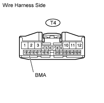 |
Disconnect the T4 ECU connector.
Measure the resistance of the wire harness side connector.
| Tester Connection | Specified Condition |
| T4-14 (BMA) - Body ground | Below 1 Ω |
|
| ||||
| OK | ||
| ||
| ||
| 10.CHECK WIRE HARNESS (TRANSMISSION CONTROL ECU - SHIFT CONTROL ACTUATOR) |
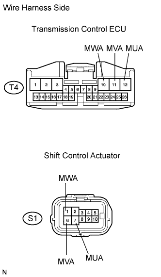 |
Disconnect the T4 ECU connector.
Measure the resistance of the wire harness side connector.
| Tester Connection | Specified Condition |
| T4-10 (MWA) - S1-1 (MWA) | Below 1 Ω |
| T4-11 (MVA) - S1-6 (MVA) | Below 1 Ω |
| T4-12 (MUA) - S1-7 (MUA) | Below 1 Ω |
| T4-10 (MWA) - Body ground | 10 kΩ or higher |
| T4-11 (MVA) - Body ground | 10 kΩ or higher |
| T4-12 (MUA) - Body ground | 10 kΩ or higher |
|
| ||||
| OK | |
|
| 11.INSPECT SHIFT CONTROL ACTUATOR |
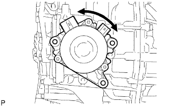 |
Remove the 3 bolts and transmission case cover.
Remove the 3 bolts.
Slightly pull the shift control actuator from the hybrid vehicle transaxle so that the shift control actuator can be turned.
Turn the shift control actuator.
|
| ||||
| OK | ||
| ||
| ||

