Home › HYBRID SYSTEM › HYBRID TRANSMISSION / TRANSAXLE › ELECTRONIC SHIFT LEVER SYSTEM

DTC    C2318    Low Voltage Error (Power Supply Malfunction)

for Preparation Click here


DESCRIPTION

The auxiliary battery voltage is applied to terminal +B when the power switch is ON (IG). The transmission control ECU outputs this DTC when the input voltage drops.

DTC No.
DTC Detection Condition
Trouble area
C2318
When both conditions below are met:
  1. Power switch ON (IG)
  2. Terminal +B voltage of the transmission control ECU is 9.3 V or less for 1 second or more.
  1. HEV fuse
  2. IGCT relay
  3. Wire harness or connector
  4. Auxiliary battery

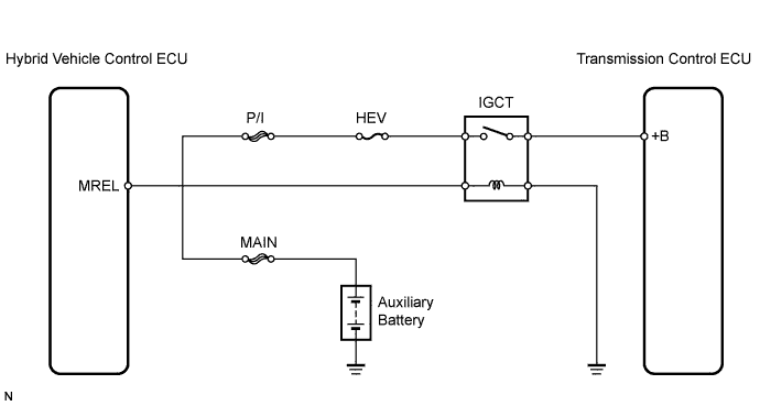
WIRING DIAGRAM


C126774E01


INSPECTION PROCEDURE

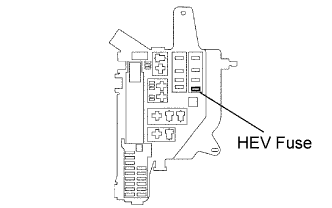
1.INSPECT FUSE (HEV)


    F044949E01
  1. Remove the HEV fuse from the engine room relay block.

  1. Measure the resistance of the fuse.

    Standard resistance:
    Below 1 Ω


NG
INSPECT FOR SHORT IN ALL COMPONENTS CONNECTED TO FUSE AND REPAIR OR REPLACE THEM IF NEEDED, AND REPLACE FUSE
OK


2.CHECK OTHER DTC OUTPUT (BESIDE C2318)
  1. Connect the Techstream to the DLC3.

  1. Turn the power switch ON (IG).

  1. Turn the Techstream on.

  1. Read the DTCs.

    Result 
    Result
    Proceed to
    No output
    A
    P3110-223
    B

    HINT:
    DTC P3110 indicates HV main relay malfunction. DTC P3110-223 indicates "IGCT relay malfunction".


B
REPAIR CIRCUIT INDICATED BY OUTPUT CODE
A


3.READ VALUE OF TECHSTREAM (IG (+B) VOLTAGE)
  1. Check the Data List for proper functioning of the transmission control ECU.

    Transmission control ECU 
    Tester Display
    Measurement Item / Range
    Normal Condition
    Diagnostic Note
    IG (+B) Voltage Value
    IG (+B) voltage value / min: 0 V, max: 20 V
    Actual power supply voltage 9 to 14 V
    -

    Standard voltage:
    9 to 14 V


OK
REPLACE TRANSMISSION CONTROL ECU
NG

REPAIR OR REPLACE HARNESS AND CONNECTOR (ENGINE ROOM RELAY BLOCK AND JUNCTION BLOCK - TRANSMISSION CONTROL ECU)