Home › BODY ELECTRICAL › DOOR LOCK › SMART KEY SYSTEM

SMART KEY SYSTEM > Vehicle is not Ready to Start when Driver Has Key

for Preparation Click here


DESCRIPTION

If the entry ignition function does not operate, insert the key into the key slot and check if the hybrid control system starts. If the hybrid control system starts (the transponder key ECU outputs a start permission to the hybrid control system and the hybrid control system starts), it can be assumed that only the entry ignition system is malfunctioning.
The certification ECU uses the indoor electrical key oscillator to send a request signal to the key when: 1) the driver's door is opened and closed, or 2) the power switch is changed from ON (ACC) to OFF or OFF to ON. Then, the key transmits its ID code to the door control receiver. The ID code, which is then sent to the certification ECU, is verified by the certification ECU and the verification result is sent to the transponder key ECU.
The transponder key ECU and the certification ECU communicate encryption codes to each other using the multiplex communication line. When the return code from the certification ECU matches the ID code in memory, the transponder key ECU sends a hybrid control system start permission signal to the hybrid control ECU. Pressing the power switch while depressing the brake pedal then starts the hybrid control system. With the vehicle stopped, pressing the power switch again stops the hybrid control system.

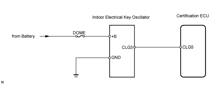
WIRING DIAGRAM


B128889E06


INSPECTION PROCEDURE

1.CHECK ENTRY DOOR LOCK AND UN LOCK OPERATION
  1. Check that the entry lock and unlock functions operate normally.

    OK:
    Entry lock and unlock functions operate normally


NG
GO TO PROBLEM SYMPTOMS TABLE
OK


2.READ VALUE OF TECHSTREAM (HALFWAY SWITCH)
  1. Check the Data List for proper functioning of the halfway switch.

    Certification ECU 
    Tester Display
    Measurement Item/Range
    Normal Condition
    Diagnostic Note
    Key Unlk Wrn SW
    Key unlock warning switch /
    ON or OFF
    OK: Key is in key slot
    OFF: No key is in key slot
    -

    OK:
    ON (key is in key slot) appears on screen.


NG
GO TO SMART KEY SYSTEM (for starting)
OK


3.PERFORM ACTIVE TEST BY TECHSTREAM (INDOOR ELECTRICAL KEY OSCILLATOR)
  1. Select the Active Test, use the Techstream to generate a control command, and then check that the oscillator operates.

    Certification ECU 
    Tester Display
    Test Part
    Control Range
    Diagnostic Note
    Fr Transmitter
    Indoor electrical key oscillator (front)
    ON / OFF
    -

    OK:
    When key is brought close to indoor electrical key oscillator, oscillator is turned ON and indicator on key illuminates.


OK
REPLACE CERTIFICATION ECU
NG


4.INSPECT FUSE (MPX-B, D/C CUT)
  1. Remove the MPX-B and D/C CUT fuses from the engine room relay block.

  1. Measure the resistance of the fuses.

    Standard resistance:
    Below 1 Ω


NG
REPLACE FUSE
OK


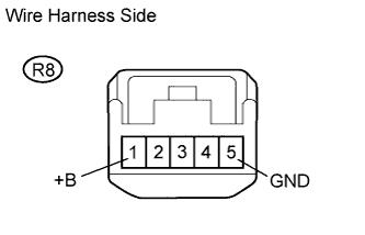
5.CHECK WIRE HARNESS (INDOOR ELECTRICAL KEY OSCILLATOR - BATTERY AND BODY GROUND)
B106249E02
  1. Disconnect the R8 oscillator connector.

  1. Measure the voltage of the wire harness side connector.

    Standard voltage:
    Tester Connection
    Specified Condition
    R8-1 (+B) - Body ground
    10 to 14 V

  1. Measure the resistance of the wire harness side connector.

    Standard resistance:
    Tester Connection
    Specified Condition
    R8-5 (GND) - Body ground
    Below 1 Ω


NG
REPAIR OR REPLACE HARNESS AND CONNECTOR
OK


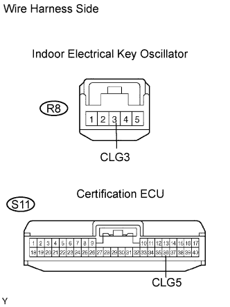
6.CHECK WIRE HARNESS (INDOOR ELECTRICAL KEY OSCILLATOR - CERTIFICATION ECU)
B079793E03
  1. Disconnect the R8 oscillator connectors.

  1. Disconnect the S11 ECU connector.

  1. Measure the resistance of the wire harness side connectors.

    Standard resistance:
    Tester Connection
    Specified Condition
    R8-3 (CLG3) - S11-36 (CLG5)
    Below 1 Ω
    R8-3 (CLG3) or S11-36 (CLG5) - Body ground
    10 kΩ or higher


NG
REPAIR OR REPLACE HARNESS AND CONNECTOR
OK


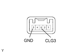
7.CHECK INDOOR ELECTRICAL KEY OSCILLATOR (CLG3 VOLTAGE)
B080048E05
  1. Measure the voltage of the oscillator connector.

    Standard voltage:
    Tester Connection
    Condition
    Specified Condition
    R8-3 (CLG3) - R8-5 (GND)
    During Active Test
    Alternating between 5 V and below 1 V


NG
REPLACE INDOOR ELECTRICAL KEY OSCILLATOR
OK

REPLACE CERTIFICATION ECU