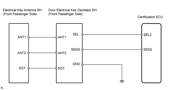
SMART KEY SYSTEM > Front Passenger Side Door Entry Unlock Function does not Operate |
| 1.CHECK MANUAL DOOR UNLOCK OPERATION |
Check that the manual door lock and unlock function operates normally.
|
| ||||
| OK | |
 |
| 2.CHECK DOOR ELECTRICAL KEY OSCILLATOR RH (SEL VOLTAGE) |
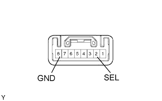 |
Measure the voltage between the terminals of the connector when the key is operated.
| Tester Connection | Condition | Specified Condition |
| D17-2 (SEL) - D17-8 (GND) | Key at least 5 m (16.4 ft.) away from door | 10 to 14 V |
| Key within 0.7 m (2.3 ft.) from door | Below 1 V |
|
| ||||
| OK | |
|
| 3.CHECK DOOR ELECTRICAL KEY OSCILLATOR RH (SENS VOLTAGE) |
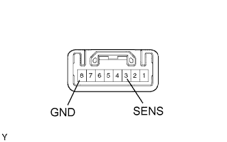 |
Measure the voltage between the terminals of the connector when the outside door handle is touched.
| Tester Connection | Condition | Specified Condition |
| D17-3 (SENS) - D17-8 (GND) | Outside door handle not touched | 10 to 14 V |
| Outside door handle touched | Below 1 V |
|
| ||||
| NG | |
|
| 4.CHECK WIRE HARNESS (DOOR ELECTRICAL KEY OSCILLATOR RH - CERTIFICATION ECU) |
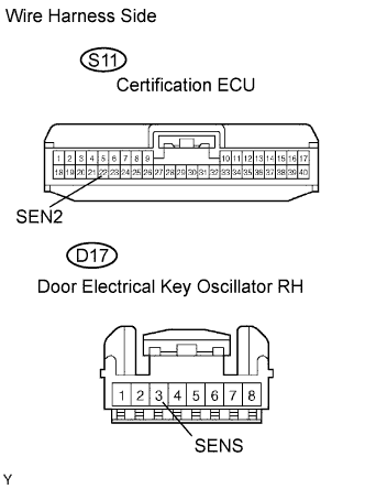 |
Disconnect the D17 oscillator connector.
Disconnect the S11 ECU connector.
Measure the resistance of the wire harness side connectors.
| Tester Connection | Specified Condition |
| D17-3 (SENS) - S11-22 (SEN2) | Below 1 Ω |
| D17-3 (SENS) or S11-22 (SEN2) - Body ground | 10 kΩ or higher |
|
| ||||
| OK | |
|
| 5.CHECK OPERATION OF DOOR ELECTRICAL KEY OSCILLATOR RH |
After replacing the door electrical key oscillator on the front passenger's side with a new one, check that the entry unlock function operates normally.
|
| ||||
| NG | |
|
| 6.CHECK WIRE HARNESS (DOOR ELECTRICAL KEY OSCILLATOR RH - ELECTRICAL KEY ANTENNA) |
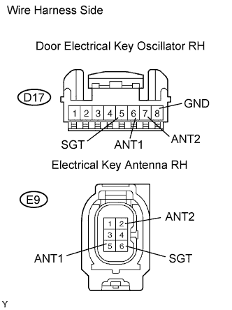 |
Disconnect the D17 oscillator connector.
Disconnect the E9 antenna connector.
Measure the resistance of the wire harness side connectors.
| Tester Connection | Specified Condition |
| D17-6 (ANT1) - E9-5 (ANT1) | Below 1 Ω |
| D17-7 (ANT2) - E9-2 (ANT2) | Below 1 Ω |
| D17-5 (SGT) - E9-6 (SGT) | Below 1 Ω |
| D17-8 (GND) - Body ground | Below 1 Ω |
| D17-6 (ANT1) or E9-5 (ANT1) - Body ground | 10 kΩ or higher |
| D17-7 (ANT2) or E9-2 (ANT2) - Body ground | 10 kΩ or higher |
| D17-5 (SGT) or E9-6 (SGT) - Body ground | 10 kΩ or higher |
|
| ||||
| OK | ||
 | ||
| ||
| 7.CHECK WIRE HARNESS (DOOR ELECTRICAL KEY OSCILLATOR RH - CERTIFICATION ECU) |
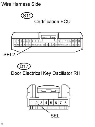 |
Disconnect the D17 oscillator connector.
Disconnect the S11 ECU connector.
Measure the resistance of the wire harness side connectors.
| Tester Connection | Specified Condition |
| D17-2 (SEL) - S11-24 (SEL2) | Below 1 Ω |
| D17-2 (SEL) or S11-24 (SEL2) - Body ground | 10 kΩ or higher |
|
| ||||
| OK | ||
| ||
| ||

