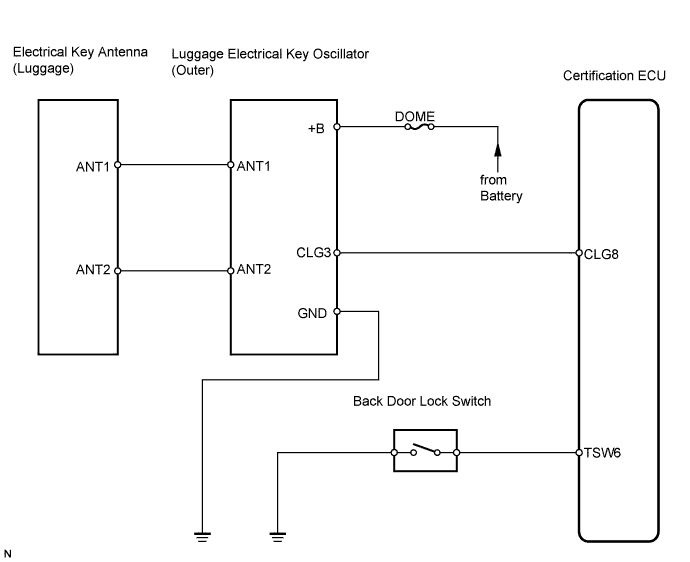
SMART KEY SYSTEM > Back Door Entry Unlock Function does not Operate |
| 1.CHECK ENTRY LOCK AND UNLOCK OPERATION |
Check that the entry lock and unlock functions operate normally.
|
| ||||
| OK | |
 |
| 2.READ VALUE OF TECHSTREAM (BACK DOOR LOCK SWITCH) |
Check the Data List for proper functioning of the back door lock switch.
| Tester Display | Measurement Item/Range | Normal Condition | Diagnostic Note |
| Tr/B-Door Lock | Trunk / Back-door lock switch / ON or OFF | ON: Back door lock switch is pushed OFF: Back door lock switch is not pushed | - |
|
| ||||
| NG | |
|
| 3.INSPECT BACK DOOR OPENER SWITCH |
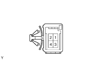 |
Disconnect the L4 switch connector.
Measure the resistance of the switch.
| Tester Connection | Condition | Specified Condition |
| 3 - 4 | Not pushed (OFF) | 10 kΩ or higher |
| 3 - 4 | Pushed (ON) | Below 1 Ω |
|
| ||||
| OK | |
|
| 4.CHECK WIRE HARNESS (CERTIFICATION ECU - BACK DOOR LOCK SWITCH AND BODY GROUND) |
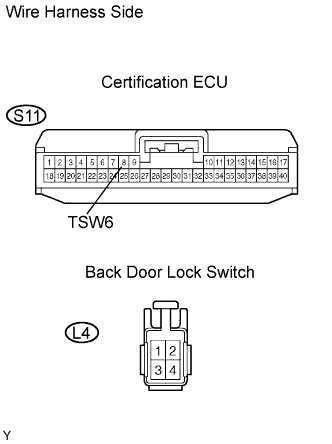 |
Disconnect the S11 ECU connector.
Disconnect the L4 switch connector.
Measure the resistance of the wire harness side connectors.
| Tester Connection | Specified Condition |
| S11-8 (TSW6) - L4-3 | Below 1 Ω |
| L4-4 - Body ground | Below 1 Ω |
|
| ||||
| OK | ||
 | ||
| ||
| 5.INSPECT ELECTRICAL KEY ANTENNA (LUGGAGE) |
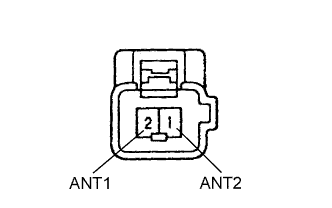 |
Measure the resistance of antenna.
| Tester Connection | Condition | Specified Condition |
| 1 (ANT2) - 2 (ANT1) | Back door lock switch pushed | Below 1 Ω |
| Back door lock switch not pushed | 10 kΩ or higher |
|
| ||||
| OK | |
|
| 6.CHECK WIRE HARNESS (LUGGAGE ELECTRICAL KEY OSCILLATOR (OUTER) - ELECTRICAL KEY ANTENNA (LUGGAGE)) |
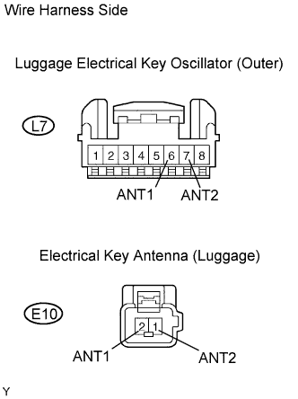 |
Disconnect the L7 oscillator connector.
Disconnect the E10 antenna connector.
Measure the resistance of the wire harness side connectors.
| Tester Connection | Specified Condition |
| L7-6 (ANT1) - E10-2 (ANT1) | Below 1 Ω |
| L7-7 (ANT2) - E10-1 (ANT2) | Below 1 Ω |
|
| ||||
| OK | |
|
| 7.CHECK WIRE HARNESS (LUGGAGE ELECTRICAL KEY OSCILLATOR (OUTER) - BODY GROUND) |
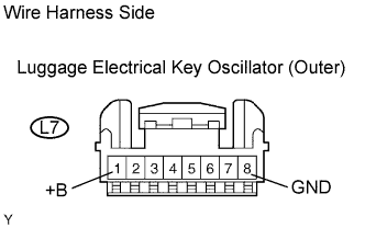 |
Disconnect the L7 oscillator connector.
Measure the voltage of the wire harness side connector.
| Tester Connection | Specified Condition |
| L7-1 (+B) - Body ground | 10 to 14 V |
Measure the resistance of the wire harness side connector.
| Tester Connection | Specified Condition |
| L7-8 (GND) - Body ground | Below 1 Ω |
|
| ||||
| OK | |
|
| 8.PERFORM ACTIVE TEST BY TECHSTREAM (LUGGAGE ELECTRICAL KEY OSCILLATOR (OUTER)) |
Select the ACTIVE TEST, use the Techstream to generate a control command, and then check that the oscillator (outer) operates.
| Tester Display | Test Part | Control Range | Diagnostic Note |
| BDoor Trnsmttr | Back door outer transmitter | ON / OFF | - |
|
| ||||
| NG | |
|
| 9.CHECK LUGGAGE ELECTRICAL KEY OSCILLATOR (OUTER) (CLG VOLTAGE) |
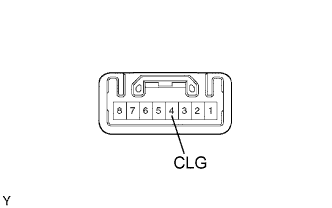 |
Remove the oscillator but do not disconnect its connector.
Measure the voltage of the connector.
| Tester Connection | Condition | Specified Condition |
| L7-4 (CLG) - Body ground | Back door lock switch OFF | Below 1 V |
| Back door lock switch ON | Alternating between 5 V and below 1 V |
|
| ||||
| OK | |
|
| 10.CHECK WIRE HARNESS (CERTIFICATION ECU- LUGGAGE ELECTRICAL KEY OSCILLATOR (OUTER)) |
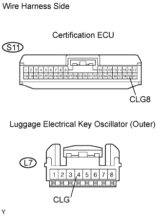 |
Disconnect the S11 ECU connector.
Disconnect the L7 oscillator connector.
Measure the resistance of the wire harness side connectors.
| Tester Connection | Specified Condition |
| S11-39 (CLG8) - L7-4 (CLG) | Below 1 Ω |
|
| ||||
| OK | ||
| ||
| ||

