HV BATTERY > REASSEMBLY |
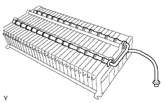
| 1. INSTALL BATTERY ROOM VENTILATION HOSE |
|
| 2. INSTALL NO. 2 FRAME WIRE |
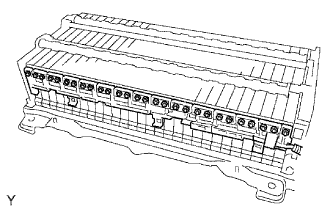 |
Install the No. 2 frame wire with new 26 nuts.
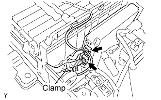 |
Connect the No. 2 frame wire connector to the battery ECU, then connect the clamp.
Connect the temperature sensor connector to the battery ECU.
| 3. INSTALL NO. 2 BATTERY SPACER |
| 4. INSTALL UPPER BATTERY CARRIER |
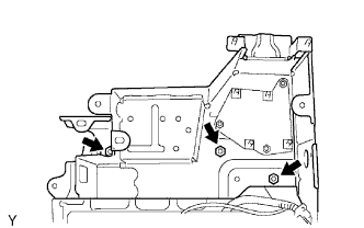 |
Install the upper battery carrier with the 3 nuts.
| 5. INSTALL BATTERY ECU |
Install the battery ECU with the 2 screws.
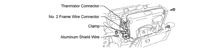
Install the aluminum shield wire of the main battery cable together with the battery ECU with a new nut.
Connect the clamp and No. 2 frame wire connector.
Connect the thermistor connector.
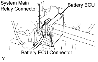 |
Connect the system main relay connector.
| 6. INSTALL NO. 1 SYSTEM MAIN RELAY |
Install the No. 1 system main relay with the 2 bolts.
Connect the system main relay connector.
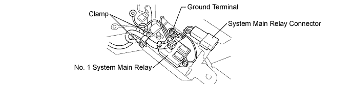
Connect the 2 clamps, then install the system main relay sub wiring harness to the upper battery carrier.
Install the ground terminal with the nut.
Install the connector.
| 7. INSTALL SYSTEM MAIN RESISTOR |
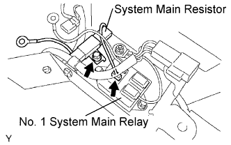 |
Install the system main resistor with the bolt.
Install the connector to the No. 1 system main relay.
| 8. INSTALL NO. 3 SYSTEM MAIN RELAY |
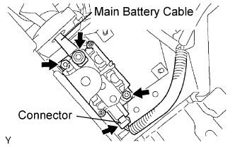 |
Connect the connector, then temporarily install the No. 3 system main relay.
Install the No. 3 system main relay with 2 new nuts.
Install the main battery cable with the nut.
| 9. INSTALL NO. 2 SYSTEM MAIN RELAY |
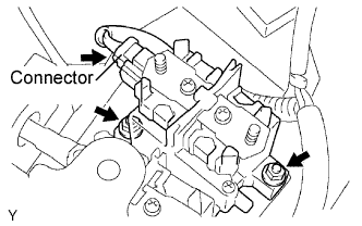 |
Install the No. 2 system main relay with the 2 nuts.
Connect the connector.
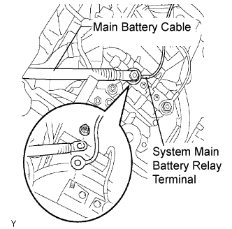 |
Temporarily install the system main relay terminal and No. 2 main battery cable terminal, in that order, and tighten a new nut.
Install the 2 terminal covers.
| 10. INSPECT CONTACT CONDITION |
Check that all the wire harnesses are correctly and securely connected on the upper battery carrier.
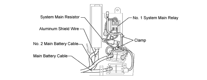
| 11. INSTALL JUNCTION BLOCK |
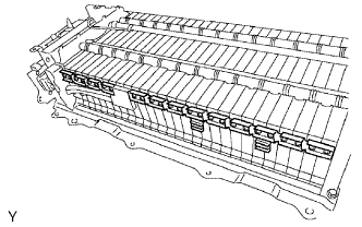 |
Install the junction block assembly with 26 new nuts.
| 12. INSTALL BATTERY PLUG |
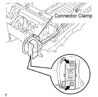 |
Temporarily fasten the service plug.
Install the service plug to the upper battery carrier with the 2 bolts.
Assemble the connector clamp.
| 13. INSTALL NO. 1 WIRE HARNESS PROTECTOR COVER |
Temporarily fasten the wire harness protector cover to the service plug.
Install the wiring harness protector cover through the service plug with 2 new nuts.
| 14. INSTALL BATTERY CLAMP PAD |
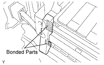 |
Install a new clamp pad (the battery carrier cushion).
| 15. INSTALL NO. 4 WIRE HARNESS PROTECTOR COVER |
| 16. INSTALL NO. 2 WIRE HARNESS PROTECTOR COVER |
| 17. INSTALL BATTERY CURRENT SENSOR |
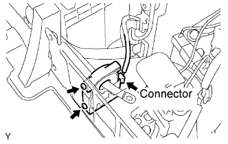 |
Install the battery current sensor with the 2 screws.
Connect the connector.
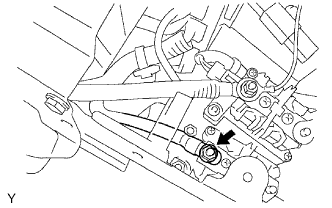 |
Install the main battery cable with a new nut.
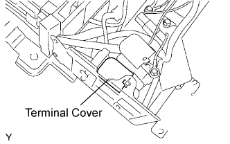 |
Install the terminal cover.
| 18. INSTALL NO. 2 MAIN BATTERY CABLE |
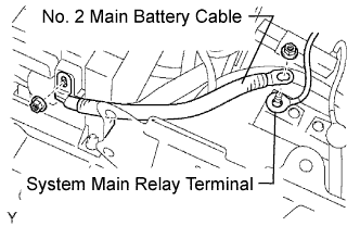 |
Temporarily install the No. 2 main battery cable to the HV battery.
Install the No. 2 main battery cable to the No. 2 frame wire with a new nut.
Temporarily install the main battery cable and system main relay terminal, in that order, to the No. 2 system main relay, then tighten the new nut.
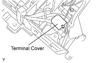 |
Install the terminal cover shown in the illustration.
| 19. INSTALL MAIN BATTERY CABLE |
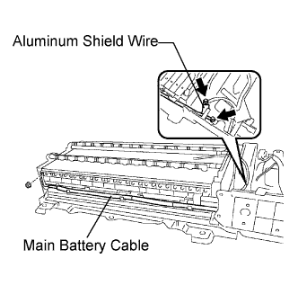 |
Temporarily install the main battery cable to the HV battery.
Install the main battery cable to the No. 2 frame wire with a new nut.
Install the main battery cable to the No. 3 system main relay with a new nut.
Install the aluminum shield wire with a new nut.
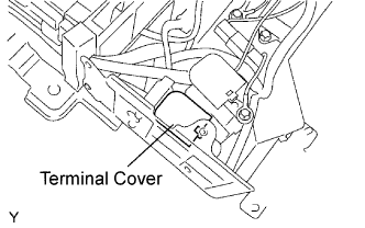 |
Install the terminal cover shown in the illustration.
| 20. INSTALL NO. 3 BATTERY CARRIER CUSHION |
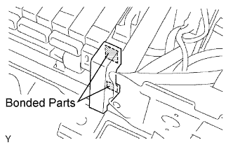 |
Degrease and clean the installation surface of the battery carrier cushion.
Install a new battery carrier cushion.
| 21. INSTALL NO. 3 WIRE HARNESS PROTECTOR COVER |
| 22. INSTALL NO. 1 WIRE HARNESS PROTECTOR COVER |
| 23. INSTALL BATTERY COVER |
Temporarily fasten the battery carrier catch bracket to the battery room ventilation hose.
Install the battery cover with the 6 bolts, 2 nuts and clip.
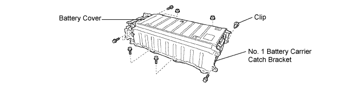
Install the protector on the battery cover.