 |
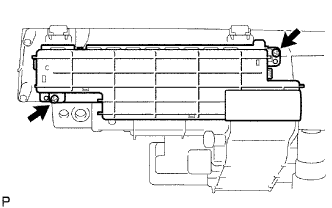
Remove the 2 screws.
COMBINATION METER > DISASSEMBLY |
| 1. REMOVE NO. 1 COMBINATION METER COVER |
|
Remove the 2 screws.
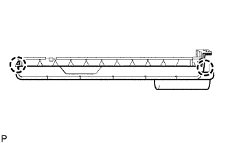 |
Detach the 2 claws, and then remove the combination meter cover.
| 2. REMOVE METER CIRCUIT PLATE |
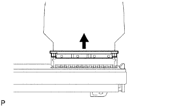 |
Pull the connector lock in the direction indicated by the arrow in the illustration and separate the No. 3 meter circuit plate from the meter circuit plate.
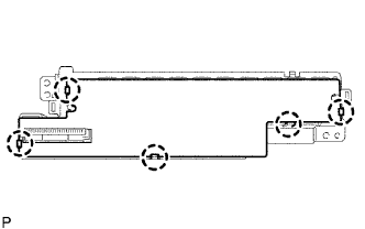 |
Detach the 5 claws, and then remove the meter circuit plate.
| 3. REMOVE NO. 2 COMBINATION METER CASE |
| 4. REMOVE NO. 2 COMBINATION METER COVER |
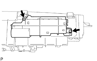 |
Remove the 2 screws.
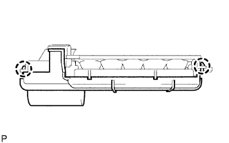 |
Detach the 2 claws, and then remove the combination meter cover.
| 5. REMOVE NO. 2 METER CIRCUIT PLATE |
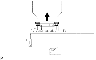 |
Pull the connector lock in the direction indicated by the arrow in the illustration and separate the No. 4 meter circuit plate from the No. 2 meter circuit plate.
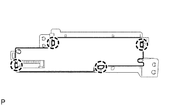 |
Detach the 4 claws, and then remove the meter circuit plate.
| 6. REMOVE NO. 3 COMBINATION METER CASE |
| 7. REMOVE NO. 1 COMBINATION METER REFLECTOR |
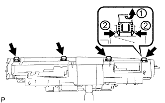 |
Remove the 4 clips.
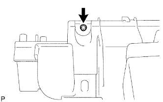 |
Remove the screw and combination meter reflector.
| 8. REMOVE NO. 3 COMBINATION METER COVER |
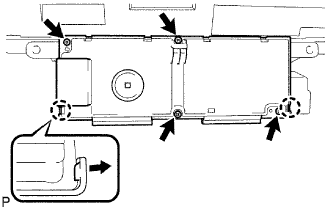 |
Remove the 4 screws.
Release the 2 claws of the cover, as shown in the illustration.
Raise the cover from the bottom and remove the combination meter cover.
| 9. REMOVE NO. 3 METER CIRCUIT PLATE |
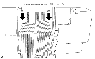 |
Pull the connector lock in the direction indicated by the arrow in the illustration, and remove the meter circuit plate.
| 10. REMOVE NO. 4 METER CIRCUIT PLATE |
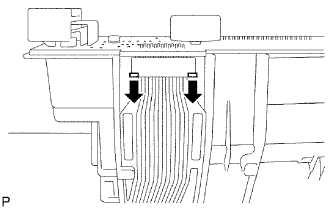 |
Pull the connector lock in the direction indicated by the arrow in the illustration, and remove the meter circuit plate.
| 11. REMOVE COMBINATION METER CASE |