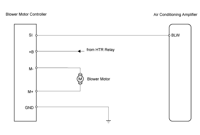
AIR CONDITIONING SYSTEM > Blower Motor Circuit |
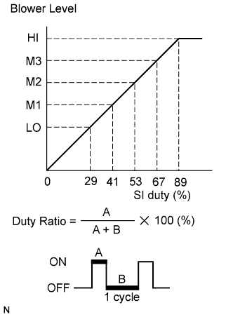
| 1.PERFORM ACTIVE TEST BY TECHSTREAM |
Connect Techstream to DLC3.
Turn the power switch ON (IG) and turn Techstream ON.
Select the item below in the Active Test and then check that the relay operates.
| Item | Test Details / Display (Range) | Diagnostic Note |
| Blower Motor | Blower motor / min.: 0 max.: 31 | - |
| Result | Proceed to |
| NG (Blower motor does not operate) | A |
| NG (Blower motor operate but does not change speed) | B |
| OK | C |
|
| ||||
|
| ||||
| A | |
 |
| 2.INSPECT BLOWER W/ FAN MOTOR SUB-ASSEMBLY |
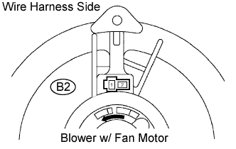 |
Remove the cooling unit motor w/ fan.
Connect the battery's positive (+) lead to terminal 1 of blower motor and negative (-) lead to terminal 2.
|
| ||||
| OK | |
|
| 3.CHECK WIRE HARNESS (BLOWER MOTOR CONTROLLER - BATTERY) |
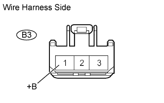 |
Disconnect the B3 controller connector.
Measure the voltage of the wire harness side connector.
| Tester Connection | Specified Condition |
| B3-1 (+B) - Body ground | 10 to 14 V |
|
| ||||
| OK | |
|
| 4.CHECK WIRE HARNESS (BLOWER MOTOR CONTROLLER - BODY GROUND) |
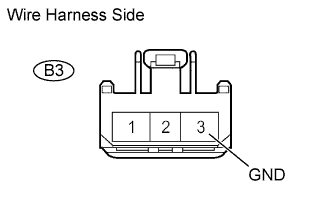 |
Disconnect the B3 controller connector.
Measure the resistance of the wire harness side connector.
| Tester Connection | Specified Condition |
| B3-3 (GND) - Body ground | Below 1 Ω |
|
| ||||
| OK | |
|
| 5.CHECK WIRE HARNESS (BLOWER MOTOR - BLOWER MOTOR CONTROLLER) |
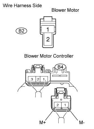 |
Disconnect the B2 motor connector.
Disconnect the B4 controller connector.
Measure the resistance of the wire harness side connectors.
| Tester Connection | Specified Condition |
| B4-1 (M-) - B2-2 | Below 1 Ω |
| B4-2 (M+) - B2-1 | Below 1 Ω |
| B4-1 (M-) - Body ground | 10 kΩ or higher |
| B4-2 (M+) - Body ground | 10 kΩ or higher |
|
| ||||
| OK | |
|
| 6.CHECK WIRE HARNESS (BLOWER MOTOR CONTROLLER - AIR CONDITIONING AMPLIFIER) |
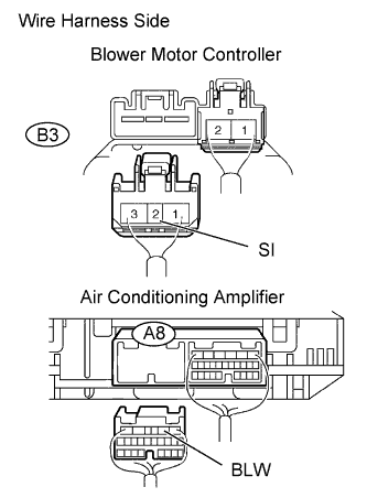 |
Disconnect the B3 controller connector.
Disconnect the A8 amplifier connector.
Measure the resistance of the wire harness side connectors.
| Tester Connection | Specified Condition |
| A8-2 (BLW) - B3-2 (SI) | Below 1 Ω |
| A8-2 (BLW) - Body ground | 10 kΩ or higher |
|
| ||||
| OK | |
|
| 7.CHECK BLOWER MOTOR CONTROLLER (BLW VOLTAGE) |
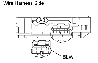 |
Disconnect the A8 amplifier connector.
Measure the voltage of the wire harness side connector.
| Tester Connection | Specified Condition |
| B3-1 (+B) - Body ground | 10 to 14 V |
|
| ||||
| OK | |
|
| 8.CHECK AIR CONDITIONING AMPLIFIER (BLW - BODY GROUND) |
|
Remove the air conditioning amplifier with its connectors still connected.
Turn the power switch ON (IG).
Turn the blower switch ON (Lo).
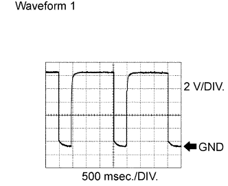 |
Using an oscilloscope, measure the waveform of the amplifier.
| Item | Content |
| Tester Connection | A8-2 (BLW) - Body ground |
| Tool Setting | 2 V/DIV., 500 msec./DIV. |
| Condition | Blower switch ON (Lo) |
|
| ||||
| OK | ||
 | ||
| ||

