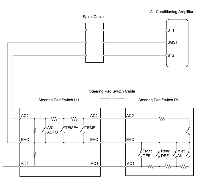
AIR CONDITIONING SYSTEM > Steering Pad Switch Circuit |
| 1.CHECK AIR CONDITIONING AMPLIFIER (ST1, ST2 VOLTAGE) |
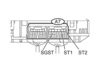 |
Remove the air conditioning with connectors still connected.
Measure the voltage of the wire harness side connectors.
| Tester Connection | Condition | Specified Condition |
| A7-2 (ST1) - A7-15 (SGST) | Power switch ON (IG) Fr. DEF switch ON | Below 0.3 V |
| A7-2 (ST1) - A7-15 (SGST) | Power switch ON (IG) Rr. DEF switch ON | 0.8 to 1.5 V |
| A7-2 (ST1) - A7-15 (SGST) | Power switch ON (IG) Recirculation/Fresh switch ON | 2.0 to 2.9 V |
| A7-1 (ST2) - A7-15 (SGST) | Power switch ON (IG) AUTO switch ON | Below 0.3 V |
| A7-1 (ST2) - A7-15 (SGST) | Power switch ON (IG) TEMP+ switch ON | 0.8 to 1.5 V |
| A7-1 (ST2) - A7-15 (SGST) | Power switch ON (IG) TEMP- switch ON | 2.0 to 2.9 V |
|
| ||||
| NG | |
 |
| 2.INSPECT STEERING PAD SWITCH LH |
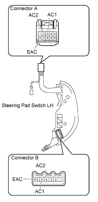 |
Remove the steering pad switch LH.
Measure the resistance of the connectors.
| Tester Connection | Condition | Specified Condition |
| A-2 (AC2) - B-4 (AC2) | Always | 1,210 Ω |
| A-7 (EAC) - B-6 (EAC) | Always | Below 1 Ω |
| A-3 (AC1) - B-5 (AC1) | Always | Below 1 Ω |
| A-2 (AC2) - A-7 (EAC) | AUTO switch ON TEMP+ switch OFF TEMP- switch OFF | Below 1 Ω |
| A-2 (AC2) - A-7 (EAC) | AUTO switch ON TEMP+ switch ON TEMP- switch OFF | 300 Ω |
| A-2 (AC2) - A-7 (EAC) | AUTO switch ON TEMP+ switch OFF TEMP- switch ON | 1,210 Ω |
| A-2 (AC2) - A-7 (EAC) | AUTO switch OFF TEMP+ switch OFF TEMP- switch OFF | 30 kΩ |
| A-2 (AC2) - A-7 (EAC) | AUTO switch OFF TEMP+ switch ON TEMP- switch OFF | 300 Ω |
| A-2 (AC2) - A-7 (EAC) | AUTO switch OFF TEMP+ switch OFF TEMP- switch ON | 1,210 Ω |
| A-7 (EAC) - A-3 (AC1) | Always | 30 kΩ |
|
| ||||
| OK | |
|
| 3.INSPECT STEERING PAD SWITCH RH |
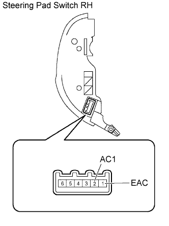 |
Remove the steering pad switch RH.
Measure the resistance of the connector.
| Tester Connection | Condition | Specified Condition |
| 2 (AC1) -1 (EAC) | Fr. DEF switch ON | Below 1 Ω |
| 2 (AC1) -1 (EAC) | Rr. DEF switch ON | 300 Ω |
| 2 (AC1) -1 (EAC) | Recirculation/Fresh switch ON | 1,210 Ω |
|
| ||||
| OK | |
|
| 4.INSPECT STEERING PAD SWITCH ASSEMBLY |
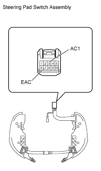 |
Connect the steering pad switch RH and LH to the steering pad switch cable.
Measure the resistance of the connector.
| Tester Connection | Condition | Specified Condition |
| 3 (AC1) - 7 (EAC) | Fr. DEF switch ON | Below 1 Ω |
| 3 (AC1) - 7 (EAC) | Rr. DEF switch ON | 300 Ω |
| 3 (AC1) - 7 (EAC) | Recirculation/Fresh switch ON | 1,210 Ω |
|
| ||||
| OK | |
|
| 5.INSPECT SPIRAL CABLE SUB-ASSEMBLY |
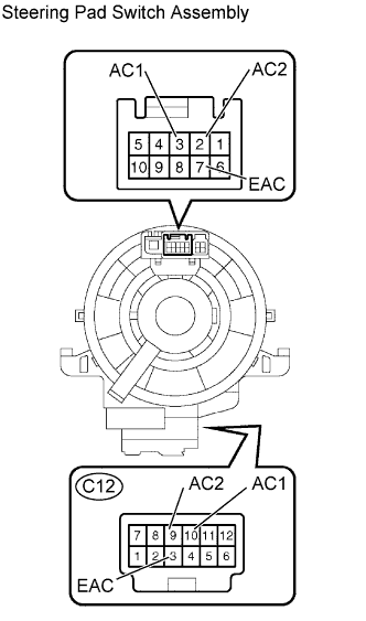 |
Remove the spiral cable.
Measure the resistance of the connectors.
| Tester Connection | Specified Condition |
| C12-3 (EAC) - 7 (EAC) | Below 1 Ω |
| C12-9 (AC2) - 2 (AC2) | Below 1 Ω |
| C12-10 (AC1) - 3 (AC1) | Below 1 Ω |
|
| ||||
| OK | |
|
| 6.CHECK WIRE HARNESS (STEERING PAD SWITCH - AIR CONDITIONING AMPLIFIER) |
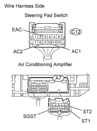 |
Disconnect the C12 steering pad connector.
Disconnect the A7 amplifier connector.
Measure the resistance of the wire harness side connectors.
| Tester Connection | Specified Condition |
| A7-2 (ST1) - C12-10 (AC1) | Below 1 Ω |
| A7-15 (SGST) - C12-3 (EAC) | Below 1 Ω |
| A7-1 (ST2) - C12-9 (AC2) | Below 1 Ω |
| A7-2 (ST1) - Body ground | 10 kΩ or higher |
| A7-15 (SGST) - Body ground | 10 kΩ or higher |
| A7-1 (ST2) - Body ground | 10 kΩ or higher |
|
| ||||
| OK | ||
 | ||
| ||
