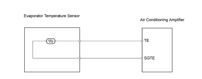
DTC B1413 Evaporator Temperature Sensor Circuit |
| DTC No. | Detection Condition | Trouble Area |
| B1413 | Open or short in evaporator temperature sensor circuit. |
|
| 1.READ VALUE OF TECHSTREAM |
Connect Techstream to DLC3.
Turn the power switch ON (IG) and turn Techstream ON.
Select the item below in the Data List, and read the display on Techstream.
| Item | Measurement Item / Display (Range) | Normal Condition | Diagnostic Note |
| Evaporator Temp Sensor | Evaporator temperature sensor / min.: -29.7°C (-21.46°F) max.: 59.55°C (139.19°F) | Actual evaporator temperature is displayed | Open in the circuit: -29.7°C (-21.46°F) Short in the circuit: 59.55°C (139.19°F) |
| Result | Proceed to |
| NG | A |
| OK (Checking from the PROBLEM SYMPTOMS TABLE) | B |
| OK (Checking from the DTC) | C |
|
| ||||
|
| ||||
| A | |
 |
| 2.CHECK AIR CONDITIONING AMPLIFIER (TE VOLTAGE) |
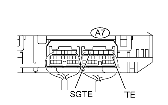 |
Remove the air conditioning amplifier with connectors still connected.
Measure the voltage of the wire harness side connector.
| Tester Connection | Condition | Specified Condition |
| A7-7 (TE) - A7-5 (SGTE) | Power switch ON (IG) at 0 °C (32°F) | 2.0 to 2.4 V |
| A7-7 (TE) - A7-5 (SGTE) | Power switch ON (IG) at 15°C (59°F) | 1.4 to 1.8 V |
| Result | Proceed to |
| NG | A |
| OK (Checking from the PROBLEM SYMPTOMS TABLE) | B |
| OK (Checking from the DTC) | C |
|
| ||||
|
| ||||
| A | |
|
| 3.INSPECT EVAPORATOR TEMPERATURE SENSOR |
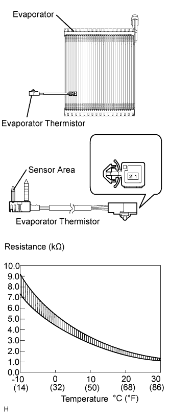 |
Remove the evaporator temperature sensor.
Measure the resistance of the sensor.
| Tester Connection | Condition | Specified Condition |
| 1 - 2 | -10°C (14°F) | 7.30 to 9.10 kΩ |
| 1 - 2 | -5°C (23°F) | 5.65 to 6.95 kΩ |
| 1 - 2 | 0°C (32°F) | 4.40 to 5.35 kΩ |
| 1 - 2 | 5°C (41°F) | 3.40 to 4.15 kΩ |
| 1 - 2 | 10°C (50°F) | 2.70 to 3.25 kΩ |
| 1 - 2 | 15°C (59°F) | 2.14 to 2.58 kΩ |
| 1 - 2 | 20°C (68°F) | 1.71 to 2.05 kΩ |
| 1 - 2 | 25°C (77°F) | 1.38 to 1.64 kΩ |
| 1 - 2 | 30°C (86°F) | 1.11 to 1.32 kΩ |
|
| ||||
| OK | |
|
| 4.CHECK WIRE HARNESS (EVAPORATOR TEMPERATURE SENSOR - AIR CONDITIONING AMPLIFIER) |
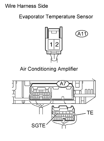 |
Disconnect the A11 sensor connector.
Disconnect the A7 amplifier connector.
Measure the resistance of the wire harness side connectors.
| Tester Connection | Specified Condition |
| A7-7 (TE) - A11-2 | Below 1 Ω |
| A7-5 (SGTE) - A11-1 | Below 1 Ω |
| A7-7 (TE) - Body ground | 10 kΩ or higher |
| A7-5 (SGTE) - Body ground | 10 kΩ or higher |
|
| ||||
| OK | ||
 | ||
| ||
