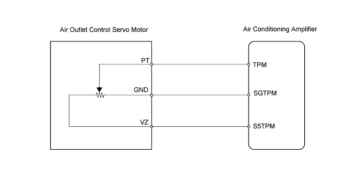
DTC B1433 Air Outlet Damper Position Sensor Circuit |
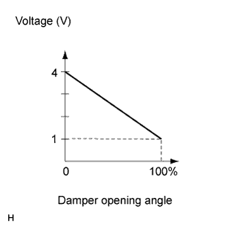
| DTC No. | Detection Condition | Trouble Area |
| B1433 | Open or short in power source circuit in air outlet damper position sensor circuit. |
|
| 1.READ VALUE OF TECHSTREAM |
Connect Techstream to DLC3.
Turn the power switch ON (IG) and turn Techstream ON.
Select the items below in the Data List, and read the displays on Techstream.
| Item | Measurement Item / Display (Range) | Normal Condition | Diagnostic Note |
| Air Outlet Damper Position | Air outlet damper position / min.: -14% max.: 113.5% | Damper is at "FACE": -10.0% Damper is at "FACE/FOOT": 12.0% Damper is at "FOOT" (Manual): 33.5% or 69.0% Damper is at "FOOT" (Auto): 49.0% or 69.0% Damper is at "FACE/DEF": 69.0% or 95.0% Damper is at "DEF": 110.0% | Open in the circuit: 50.0% |
| Air Outlet Damper Target | Air outlet damper target position / min.: -14% max.: 113.5% | Damper is at "FACE": -10.0% Damper is at "FACE/FOOT": 12.0% Damper is at "FOOT" (Manual): 33.5% or 69.0% Damper is at "FOOT" (Auto): 49.0% or 69.0 % Damper is at "FACE/DEF": 69.0% or 95.0% Damper is at "DEF": 110.0% | Open in the circuit: 50.0% |
| Result | Proceed to |
| NG | A |
| OK (Checking from the PROBLEM SYMPTOMS TABLE) | B |
| OK (Checking from the DTC) | C |
|
| ||||
|
| ||||
| A | |
 |
| 2.CHECK AIR CONDITIONING AMPLIFIER (TPM VOLTAGE) |
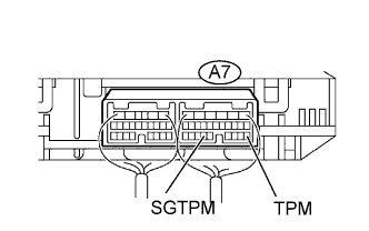 |
Remove the air condition amplifier with connectors still connected.
Measure the voltage of the wire harness side connector.
| Tester Connection | Condition | Specified Condition |
| A7-18 (TPM) - A7-23 (SGTPM) | Power switch ON (IG) FACE position | 3.97 to 4.07 V |
| A7-18 (TPM) - A7-23 (SGTPM) | Power switch ON (IG) DEF position | 0.97 to 1.03 V |
| Result | Proceed to |
| NG | A |
| OK (Checking from the PROBLEM SYMPTOMS TABLE) | B |
| OK (Checking from the DTC) | C |
|
| ||||
|
| ||||
| A | |
|
| 3.INSPECT AIR OUTLET CONTROL SERVO MOTOR |
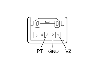 |
Remove the air outlet control servo motor.
Measure the resistance of the servo motor.
| Tester Connection | Specified Condition |
| A16-1 (VZ) - A16-2 (GND) | 4.2 to 7.2 kΩ |
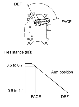 |
Measure the resistance of the servo motor.
| Tester Connection | Condition | Specified Condition |
| A16-3 (PT) - A16-2 (GND) | DEF position | 0.6 to1.1 kΩ |
| A16-3 (PT) - A16-2 (GND) | FACE position | 3.6 to 6.7 kΩ |
|
| ||||
| OK | |
|
| 4.CHECK WIRE HARNESS (AIR OUTLET CONTROL SERVO MOTOR - AIR CONDITIONING AMPLIFIER) |
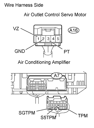 |
Disconnect the A16 servo connector.
Disconnect the A7 amplifier connector.
Measure the resistance of the wire harness side connectors.
| Tester Connection | Specified Condition |
| A7-18 (TPM) - A16-3 (PT) | Below 1 Ω |
| A7-23 (SGTPM) - A16-2 (GND) | Below 1 Ω |
| A7-11 (S5TPM) - A16-1 (VZ) | Below 1 Ω |
| A7-18 (TPM) - Body ground | 10 kΩ or higher |
| A7-23 (SGTPM) - Body ground | 10 kΩ or higher |
| A7-11 (S5TPM) - Body ground | 10 kΩ or higher |
|
| ||||
| OK | ||
 | ||
| ||
