FRONT SUSPENSION LOWER NO. 1 ARM > REMOVAL |
| 1. PLACE FRONT WHEELS FACING STRAIGHT AHEAD |
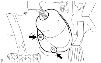
| 2. REMOVE COLUMN HOLE COVER SILENCER SHEET |
|
Fold back the floor carpet and remove the 2 clips and column hole cover silencer sheet.
| 3. DISCONNECT STEERING SLIDING YOKE SUB-ASSEMBLY |
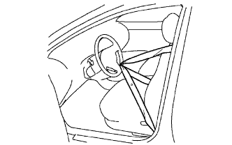 |
Fix the steering wheel with the seat belt in order to prevent rotation and damage to the spiral cable.
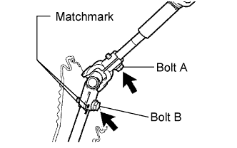 |
Put matchmarks in the sliding yoke and intermediate shaft.
Loosen the bolt labeled A and remove the bolt labeled B to separate the sliding yoke.
| 4. REMOVE FRONT WHEEL |
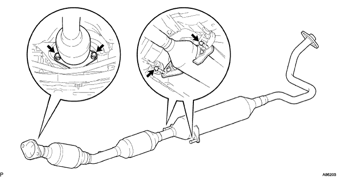
| 5. REMOVE FRONT EXHAUST PIPE ASSEMBLY |
Remove the 2 bolts and 2 compression springs.
Remove the front exhaust pipe from the 2 exhaust pipe supports.
Remove the gasket from the exhaust manifold.
| 6. REMOVE FRONT AXLE HUB NUT LH |
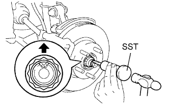 |
Using SST and a hammer, unstake the axle hub nut.
Using a 30 mm socket wrench, remove the axle hub nut.
| 7. REMOVE FRONT AXLE HUB NUT RH |
| 8. DISCONNECT NO. 2 TIE ROD END SUB-ASSEMBLY |
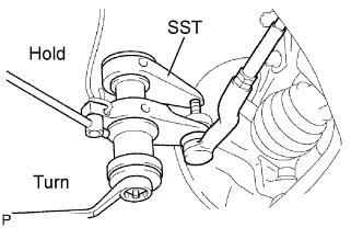 |
Remove the clip and castle nut.
Using SST, disconnect the tie rod end from the steering knuckle.
| 9. DISCONNECT NO. 1 TIE ROD END SUB-ASSEMBLY |
| 10. DISCONNECT FRONT SUSPENSION LOWER NO. 1 ARM SUB-ASSEMBLY LH |
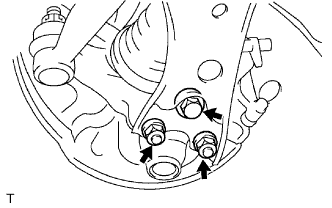 |
Remove the bolt and 2 nuts.
Lower the front suspension lower No. 1 arm and disconnect it from the front lower ball joint.
| 11. REMOVE FRONT STABILIZER LINK ASSEMBLY |
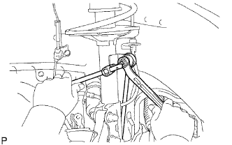 |
Remove the nuts and disconnect the stabilizer link LH and RH from the front shock absorber with coil spring.
| 12. DISCONNECT FRONT SUSPENSION LOWER NO. 1 ARM SUB-ASSEMBLY RH |
| 13. REMOVE FRONT AXLE ASSEMBLY LH |
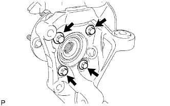 |
Remove the 4 bolts, dust cover and front axle hub.
| 14. REMOVE FRONT AXLE ASSEMBLY RH |
| 15. REMOVE FRONT DRIVE SHAFT ASSEMBLY LH |
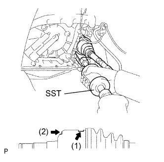 |
Remove the front fender apron seal.
Hook the SST claw at position (1) in the illustration to remove the front drive shaft.
| 16. REMOVE FRONT DRIVE SHAFT ASSEMBLY RH |
| 17. DISCONNECT FRONT SUSPENSION CROSSMEMBER SUB-ASSEMBLY |
| 18. REMOVE FRONT SUSPENSION LOWER NO. 1 ARM SUB-ASSEMBLY LH |
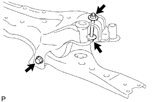 |
Remove the 2 bolts, nut and front suspension lower No. 1 arm.