Home › SUSPENSION & AXLE › SUSPENSION › FRONT LOWER BALL JOINT

FRONT LOWER BALL JOINT > REMOVAL

for Preparation Click here


HINT:
  1. Use the same procedures for the RH side and LH side.
  2. The procedures listed below are for the LH side.


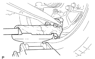
1. INSPECT FRONT LOWER BALL JOINT ASSEMBLY LH


    C054719E03
  1. Jack up the front part of the vehicle.

  1. Move the front suspension lower No. 1 arm up and down to check vertical looseness of the lower ball joint front.

    HINT:
    Wrap a cloth around the wooden block to prevent damage to the bolt and nuts.


2. REMOVE FRONT WHEEL


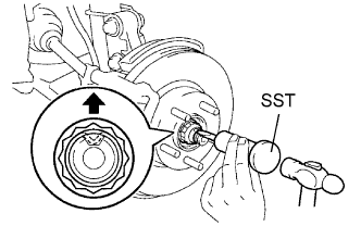
3. REMOVE FRONT AXLE HUB NUT LH


    F047428E01
  1. Using SST and a hammer, unstake the axle hub nut.

    SST
    09930-00010  

    NOTICE:
    1. Place SST on the flat part of the nut's recess.
    2. Do not grind the SST tip with a grinder or equivalent.
    3. Unstake the front axle hub nut completely when removing it.
    4. Do not damage the front drive shaft LH threads.

  1. Using a 30 mm socket wrench, remove the axle hub nut.


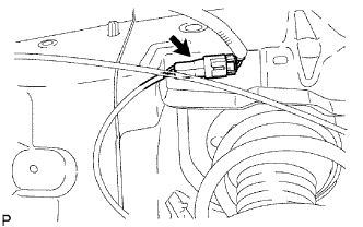
4. DISCONNECT FRONT SPEED SENSOR LH


    F046175E01
  1. Disconnect the sensor connector.


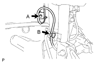
    F046179E02
  1. Remove the 2 bolts (A and B) and 2 sensor clamps from the body and front shock absorber.
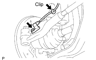
    HINT:
    The bolt B is tightened together with the brake flexible hose clamp.


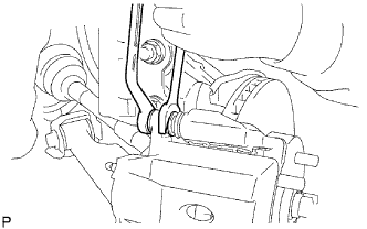
    F047471E01
  1. Remove the clip from the front shock absorber.

  1. Remove the bolt and sensor.

    NOTICE:
    Do not allow foreign matter to attach to the tip or connecting portion of the speed sensor.


5. DISCONNECT FRONT DISC BRAKE CALIPER ASSEMBLY LH


    F046161E01
  1. Remove the union bolt and gasket, and disconnect the No. 1 flexible hose from the front disc brake cylinder.

  1. Hold the front disc brake cylinder slide pin using a wrench. Remove the 2 bolts and separate the front disc brake cylinder.


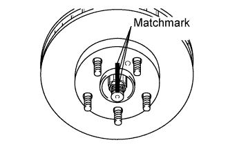
6. REMOVE FRONT DISC


F101070E01

HINT:
Put matchmarks on the disc and axle hub.


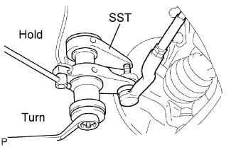
7. DISCONNECT NO. 2 TIE ROD END SUB-ASSEMBLY


    F047429E01
  1. Remove the clip and castle nut.

  1. Using SST, disconnect the tie rod end from the steering knuckle.

    SST
    09628-00011  

    NOTICE:
    1. Do not damage the front disc brake dust cover.
    2. Be sure to hang the tie rod end with a string to prevent SST from dropping.
    3. Do not damage the ball joint dust cover.
    4. Do not damage the steering knuckle.
    5. Securely hang SST to the spacer of the steering knuckle.
    6. Replace the steering knuckle with a new one if the spacer comes off the steering knuckle.


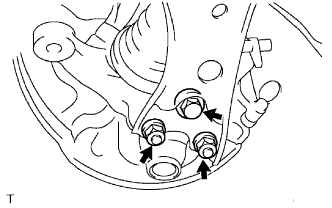
8. DISCONNECT FRONT SUSPENSION LOWER NO. 1 ARM SUB-ASSEMBLY LH


    C080293E01
  1. Remove the bolt and 2 nuts.

  1. Lower the front suspension lower No. 1 arm and disconnect if from the front lower ball joint.


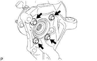
9. REMOVE FRONT AXLE ASSEMBLY LH


    G028521E01
  1. Remove the 4 bolts, dust cover and front axle hub.


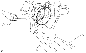
10. REMOVE FRONT NO. 1 WHEEL BEARING DUST DEFLECTOR LH


    G028520E01
  1. Mount the steering knuckle in a soft vise.

  1. Using a screwdriver, remove the deflector from the steering knuckle.

    NOTICE:
    Be careful not to damage the steering knuckle.


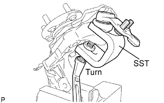
11. REMOVE FRONT LOWER BALL JOINT ASSEMBLY LH


    F046084E01
  1. Remove the clip and the castle nuts.

  1. Using SST, remove the lower ball joint front.

    SST
    09611-36020  

    NOTICE:
    1. Do not damage the steering knuckle.
    2. Securely hang SST to the spacer of the steering knuckle.
    3. Replace the steering knuckle with a new one if the spacer comes off the steering knuckle.