AIRBAG SYSTEM > SYSTEM DESCRIPTION |
| SRS AIRBAG SYSTEM OUTLINE |
FRONTAL COLLISION
The driver and front passenger airbag are designed to supplement seat belts in the event of a front collision in order to help reduce shock to the head and chest of the driver and front passenger.
Frontal collisions are detected by the center airbag sensor and two front airbag sensors. The driver and front passenger airbag and the seat belt pretensioner then operate simultaneously.
Electrical deceleration sensors are built into the two front airbag sensors in the engine compartment in order to detect the severity of the impact during the initial stage of the collision. The deployment of the driver and front passenger airbags are controlled in two stages according to the severity of the impact.
SIDE COLLISION
The front seat airbag and curtain shield airbag are designed to help reduce shock to the driver, front passenger and rear outer passenger. The curtain shield airbag was designed to help reduce shock to the front and rear passengers in the event of a side collision.
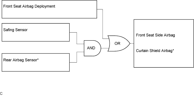
Side collisions are detected by the side airbag sensor installed in the bottom of the center pillar and the rear airbag sensor installed in the bottom of the rear pillar. Front side collisions are detected by the side airbag sensor, causing the front seat side airbag and curtain shield airbag to deploy simultaneously. Rear side collisions are detected by the rear airbag sensor to deploy only the curtain shield airbag.
| CONSTRUCTION AND OPERATION |
FRONT AIRBAG SENSOR
The front airbag sensors are installed on the right and left side members.
The deceleration sensor and safing sensor are built into the airbag sensor front and distortion that is created in the sensor is converted into an electric signal based on the vehicle deceleration rate during a frontal collision. Accordingly, the extent of the initial collision can be detected in detail.
SIDE AIRBAG SENSOR
The side airbag sensors are installed on the right and left center pillars.
The side airbag sensor consists of the deceleration sensor, safing sensor, ignition control circuit, and diagnostic circuit. The side airbag sensor receives signals from the deceleration sensor and determines whether the front seat side airbag and curtain shield airbag should be activated, and diagnoses system malfunctions simultaneously.
REAR AIRBAG SENSOR
The rear airbag sensor is installed on the bottom of the right and left rear pillars respectively.
The deceleration sensor and safing sensor are built into the rear airbag sensor and the distortion that is created in the sensor is converted into an electric signal based on the vehicle deceleration rate during a rear side collision.
CENTER AIRBAG SENSOR
General
Deceleration sensor and ignition control circuit
Safing sensor
Electronic safing sensor
Back-up power source
Diagnostic circuit
Memory circuit
SRS WARNING LIGHT
The SRS warning light is located on the combination meter. The SRS warning light informs the driver of detected malfunctions in the diagnostic circuit of the center airbag sensor or the SRS airbag system. Under normal operating conditions when the power switch is turned on, the SRS warning light comes on for approximately 6 seconds and then goes off.
| DEPLOYMENT CONDITION |
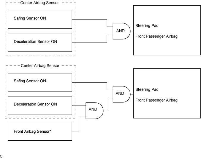
The center airbag sensor determines whether or not ignition is necessary based on signals from the deceleration sensor and the front airbag sensor*. If the deceleration sensor, front airbag sensor* and safing sensor turn on simultaneously, current flows to the squibs to deploy the SRS as shown in the illustration below.
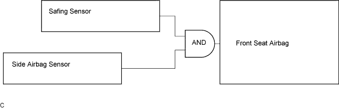
The center airbag sensor determines whether or not ignition is necessary based on signals from the side airbag sensor. If the side airbag sensor and safing sensor turn on simultaneously, current flows to the squib to deploy the SRS as shown in the illustration below.
The center airbag sensor determines whether or not ignition is necessary based on signals from the rear airbag sensor. If the rear airbag sensor and safing sensor turn on simultaneously, current flows to the squib to deploy the SRS as shown in the illustration below.