Home › BODY › WINDSHIELD / WINDOWGLASS › POWER WINDOW CONTROL SYSTEM

POWER WINDOW CONTROL SYSTEM > INSPECTION

for Preparation Click here


1. INSPECT POWER WINDOW REGULATOR MASTER SWITCH ASSEMBLY


  1. Measure the resistance of the switch when the switch is operated.
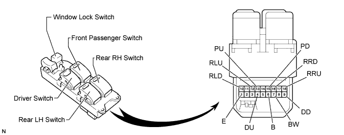

    E124624E02


    Standard resistance:
    Driver switch:

    Tester Connection
    Window Lock Switch Condition
    Power Window Switch Condition
    Specified Condition
    1 (E) - 9 (DD)
    Always
    (ON / OFF)
    UP
    Below 1 Ω
    4 (DU) - 7 (BW)
    1 (E) - 9 (DD)
    Always
    (ON / OFF)
    AUTO UP
    Below 1 Ω
    4 (DU) - 7 (BW)
    1 (E) - 4 (DU)
    Always
    (ON / OFF)
    OFF
    Below 1 Ω
    1 (E) - 9 (DD)
    1 (E) - 4 (DU)
    Always
    (ON / OFF)
    DOWN
    Below 1 Ω
    7 (BW) - 9 (DD)
    1 (E) - 4 (DU)
    Always
    (ON / OFF)
    AUTO DOWN
    Below 1 Ω
    7 (BW) - 9 (DD)
    Passenger switch:

    Tester Connection
    Window Lock Switch Condition
    Power Window Switch Condition
    Specified Condition
    1 (E) - 15 (PD)
    OFF
    UP
    Below 1 Ω
    6 (B) - 13 (PU)
    1 (E) - 13 (PU)
    OFF
    OFF
    Below 1 Ω
    1 (E) - 15 (PD)
    1 (E) - 13 (PU)
    OFF
    DOWN
    Below 1 Ω
    6 (B) - 15 (PD)
    1 (E) - 15 (PD)
    ON
    UP
    10 kΩ or higher
    6 (B) - 13 (PU)
    Below 1 Ω
    13 (PU) - 15 (PD)
    ON
    OFF
    Below 1 Ω
    1 (E) - 13 (PU)
    ON
    DOWN
    10 kΩ or higher
    6 (B) - 15 (PD)
    Below 1 Ω
    Rear LH switch:

    Tester Connection
    Window Lock Switch Condition
    Power Window Switch Condition
    Specified Condition
    1 (E) - 10 (RLD)
    OFF
    UP
    Below 1 Ω
    6 (B) - 12 (RLU)
    1 (E) - 12 (RLU)
    OFF
    OFF
    Below 1 Ω
    1 (E) - 10 (RLD)
    1 (E) - 12 (RLU)
    OFF
    DOWN
    Below 1 Ω
    6 (B) - 10 (RLD)
    1 (E) - 10 (RLD)
    ON
    UP
    10 kΩ or higher
    6 (B) - 12 (RLU)
    Below 1 Ω
    12 (RLU) - 10 (RLD)
    ON
    OFF
    Below 1 Ω
    1 (E) - 12 (RLU)
    ON
    DOWN
    10 kΩ or higher
    6 (B) - 10 (RLD)
    Below 1 Ω
    Rear RH switch:

    Tester Connection
    Window Lock Switch Condition
    Power Window Switch Condition
    Specified Condition
    1 (E) - 16 (RRD)
    OFF
    UP
    Below 1 Ω
    6 (B) - 18 (RRU)
    1 (E) - 18 (RRU)
    OFF
    OFF
    Below 1 Ω
    1 (E) - 16 (RRD)
    1 (E) - 18 (RRU)
    OFF
    DOWN
    Below 1 Ω
    6 (B) - 16 (RRD)
    1 (E) - 16 (RRD)
    ON
    UP
    10 kΩ or higher
    6 (B) - 18 (RRU)
    Below 1 Ω
    18 (RRU) - 16 (RRD)
    ON
    OFF
    Below 1 Ω
    1 (E) - 18 (RRU)
    ON
    DOWN
    10 kΩ or higher
    6 (B) - 16 (RRD)
    Below 1 Ω

    1. If the result is not as specified, replace the master switch assembly.
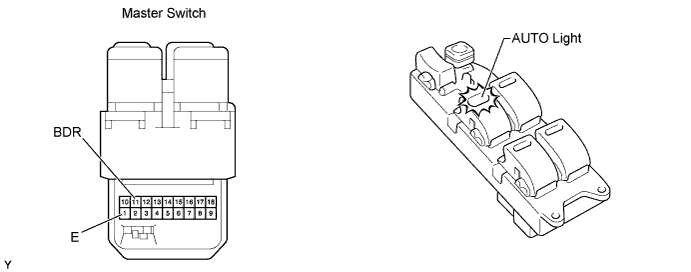


  1. Apply battery voltage to the master switch and check that the AUTO light illuminates.


    E124625E01

    OK:
    Measurement Condition
    Specified Condition
    Battery positive (+) → Terminal 11 (BDR)
    Battery negative (-) → Terminal 1 (E)
    AUTO light illuminates

    1. If the result is not as specified, replace the master switch assembly.
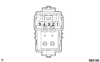


2. INSPECT POWER WINDOW REGULATOR SWITCH ASSEMBLY


    B063163
  1. Measure the resistance of the switch when the switch is operated.

    Standard resistance:
    Tester Connection
    Switch Condition
    Specified Condition
    1 - 2
    3 - 4
    UP
    Below 1 Ω
    1 - 2
    3 - 5
    OFF
    Below 1 Ω
    1 - 4
    3 - 5
    DOWN
    Below 1 Ω

    1. If the result is not as specified, replace the regulator switch assembly.


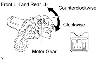
3. INSPECT POWER WINDOW REGULATOR MOTOR ASSEMBLY (for Front LH and Rear LH)


    B086401E06
  1. Apply battery voltage to connector terminals 1 and 2.

    NOTICE:
    Do not apply battery voltage to any terminals except terminals 1 and 2.

  1. Check that the motor gear rotates smoothly as follows.
    OK 
    Measurement Condition
    Specified Condition
    Battery positive (+) → Terminal 2
    Battery negative (-) → Terminal 1
    Motor gear rotates clockwise
    Battery positive (+) → Terminal 1
    Battery negative (-) → Terminal 2
    Motor gear rotates counterclockwise
    If the result is not as specified, replace the regulator motor assembly.


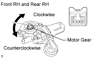
4. INSPECT POWER WINDOW REGULATOR MOTOR ASSEMBLY (for Front RH and Rear RH)


    B086400E05
  1. Apply battery voltage to connector terminals 1 and 2.

    NOTICE:
    Do not apply battery voltage to any terminals except terminals 1 and 2.

  1. Check that the motor gear rotates smoothly as follows.
    OK 
    Measurement Condition
    Specified Condition
    Battery positive (+) → Terminal 1
    Battery negative (-) → Terminal 2
    Motor gear rotates clockwise
    Battery positive (+) → Terminal 2
    Battery negative (-) → Terminal 1
    Motor gear rotates counterclockwise
    If the result is not as specified, replace the regulator motor assembly.