STEERING GEAR > REMOVAL |
| 1. PLACE FRONT WHEELS FACING STRAIGHT AHEAD |
| 2. DISCONNECT CABLE FROM NEGATIVE BATTERY TERMINAL |
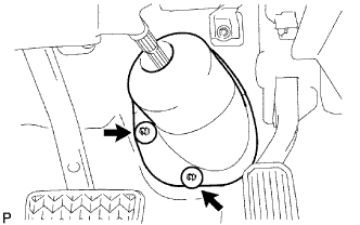
| 3. REMOVE COLUMN HOLE COVER SILENCER SHEET |
|
Fold back the floor carpet and remove the 2 clips and column hole cover silencer sheet.
| 4. SEPARATE STEERING SLIDING YOKE SUB-ASSEMBLY |
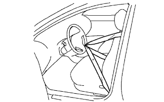 |
Fix the steering wheel with the seat belt in order to prevent rotation and damage to the spiral cable.
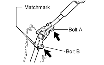 |
Put matchmarks in the sliding yoke and intermediate shaft.
Loosen the bolt labeled A and remove the bolt labeled B to separate the sliding yoke.
| 5. DISCONNECT NO. 1 STEERING COLUMN HOLE COVER SUB-ASSEMBLY |
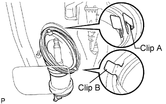 |
Remove the clip labeled A and disconnect the hole cover from the body.
| 6. REMOVE FRONT WHEELS |
| 7. DISCONNECT NO. 2 TIE ROD END SUB-ASSEMBLY |
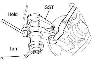 |
Remove the clip and castle nut.
Using SST, disconnect the tie rod end from the steering knuckle.
| 8. DISCONNECT NO. 1 TIE ROD END SUB-ASSEMBLY |
| 9. REMOVE FRONT STABILIZER LINK ASSEMBLY LH |
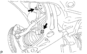 |
Remove the 2 nuts and front stabilizer link LH.
| 10. REMOVE FRONT STABILIZER LINK ASSEMBLY RH |
| 11. REMOVE FRONT NO. 1 STABILIZER BRACKET LH |
Remove the 2 bolts and the No. 1 stabilizer bracket from the front suspension crossmember.
| 12. REMOVE FRONT NO. 1 STABILIZER BRACKET RH |
| 13. REMOVE STEERING INTERMEDIATE SHAFT |
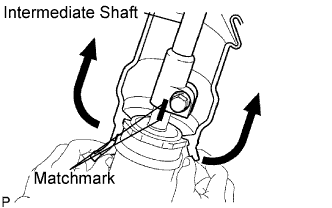 |
Move the No. 1 column hole cover to the upper side of the vehicle and put matchmarks on the intermediate shaft and steering gear.
Remove the bolt and remove the intermediate shaft from the inside of the vehicle.
Remove the No. 1 column hole cover from the steering gear.
| 14. REMOVE STEERING GEAR ASSEMBLY |
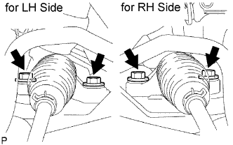 |
Remove the 4 bolts and steering gear from the left side of the vehicle.