 |
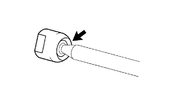
Fill up the ball joints of the RH and LH rack ends with molybdenum disulfide lithium base grease.
STEERING GEAR > REASSEMBLY |
| 1. INSTALL STEERING RACK END SUB-ASSEMBLY |
|
Fill up the ball joints of the RH and LH rack ends with molybdenum disulfide lithium base grease.
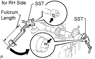 |
Using 2 SST, hold the steering rack LH side and install the rack end (for RH side).
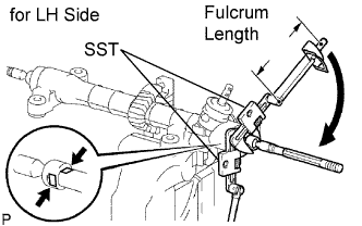 |
Using 2 SST, install the rack end (for LH side).
| 2. INSTALL NO. 2 STEERING RACK BOOT |
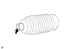 |
Apply silicon grease to the inside of the small opening of the boot.
Install the boot in the groove on the rack housing.
| 3. INSTALL NO. 1 STEERING RACK BOOT |
| 4. INSTALL NO. 2 STEERING RACK BOOT CLAMP |
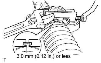 |
Install a new clamp to the boot.
While pushing SST to the rack housing, pinch the clamp so that the clearance is within specification.
| 5. INSTALL NO. 1 STEERING RACK BOOT CLAMP |
| 6. INSTALL STEERING RACK BOOT CLIP |
Using pliers, install the 2 rack boot clips to the RH and LH rack boots.
| 7. INSPECT STEERING GEAR ASSEMBLY |
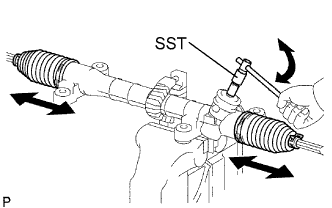 |
Using SST, turn the pinion shaft and check that the RH and LH rack boots expand and contract smoothly, reinstall it with a new rack boot clamp.
| 8. INSTALL TIE ROD END SUB-ASSEMBLY LH |
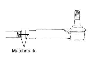 |
Screw the lock nut and tie rod end LH on the rack end unit the matchmarks are aligned and temporarily tighten the lock nut.
| 9. REMOVE TIE ROD END SUB-ASSEMBLY RH |