 |
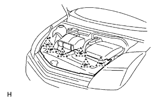
Remove the 6 clips and radiator support opening cover.
AIR FUEL RATIO SENSOR > REMOVAL |
| 1. PRECAUTION |
| 2. REMOVE RADIATOR SUPPORT OPENING COVER |
|
Remove the 6 clips and radiator support opening cover.
| 3. REMOVE ENGINE UNDER COVER LH |
| 4. REMOVE ENGINE UNDER COVER RH |
| 5. DRAIN COOLANT (for Inverter) |
Remove the transaxle-side reserve tank cap.
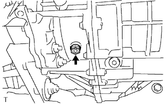 |
Remove the plug shown in the illustration and drain the coolant into a container.
Install the plug with a new gasket.
| 6. REMOVE REAR NO. 2 FLOOR BOARD |
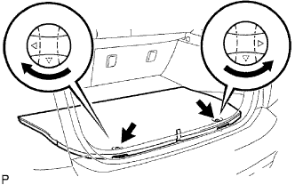 |
Unlock the 2 washer tank cover knobs, and then remove the rear floor board.
| 7. REMOVE REAR DECK FLOOR BOX |
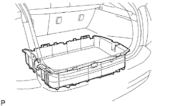 |
Remove the rear deck floor box from the vehicle.
| 8. REMOVE REAR NO. 3 FLOOR BOARD |
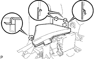 |
Detach the 4 claws, and then remove the floor board.
| 9. DISCONNECT CABLE FROM NEGATIVE BATTERY TERMINAL |
| 10. REMOVE SERVICE PLUG GRIP |
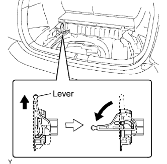 |
Slide up the lever of the service plug grip. Remove the service plug grip while turning the lever to the left.
Insulate the service plug with insulating tape.
| 11. REMOVE FRONT WIPER ARM COVER |
| 12. REMOVE FRONT WIPER ARM LH |
Remove the 2 nuts and FR wiper arm LH.
| 13. REMOVE FRONT WIPER ARM RH |
Remove the nut and FR wiper arm RH.
| 14. REMOVE HOOD TO COWL TOP SEAL |
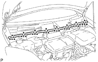 |
Detach the 8 clips and remove the hood to cowl top seal.
| 15. REMOVE COWL TOP VENTILATOR LOUVER LH |
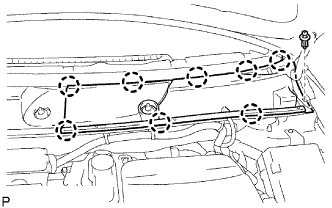 |
Detach the 8 claws and clip, and remove the cowl top ventilator louver LH.
| 16. REMOVE COWL TOP VENTILATOR LOUVER RH |
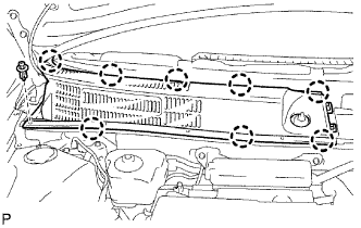 |
Detach the 8 claws and clip, and remove the cowl top ventilator louver RH.
| 17. REMOVE WINDSHIELD WIPER MOTOR AND LINK ASSEMBLY |
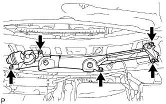 |
Disconnect the connector.
Remove the 5 bolts and wiper motor & link.
| 18. REMOVE FRONT COWL TOP PANEL OUTER |
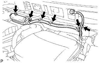 |
Remove the 2 bolts and disconnect the No. 2 engine room relay block.
Remove the 4 wire harness clamps.
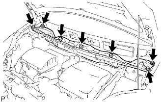 |
Remove the 7 bolts and panel.
| 19. REMOVE INVERTER COVER |
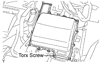 |
Using a T30 "torx" socket, remove the screw.
Remove the 12 bolts and inverter cover.
| 20. VERIFY THAT VOLTAGE OF INVERTER WITH CONVERTER IS 0 V |
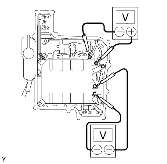 |
Using a voltmeter, measure the voltage of the high voltage DC line.
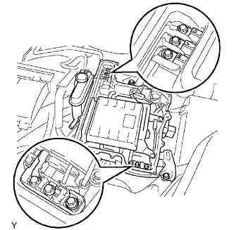 |
Using the voltmeter, measure the voltage between the terminals of the three phase connector (U - V, V - W, U - W).
| 21. DISCONNECT NO. 2 INVERTER COOLING HOSE |
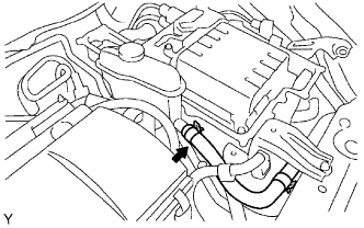 |
| 22. DISCONNECT NO. 1 INVERTER COOLING HOSE |
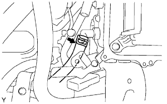 |
| 23. DISCONNECT NO. 6 INVERTER COOLING HOSE |
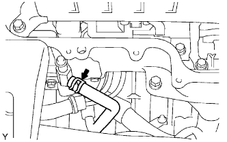 |
| 24. DISCONNECT NO. 1 CIRCUIT BREAKER SENSOR |
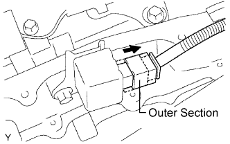 |
Move the outer section to the wire harness side as illustrated, and then disconnect the circuit breaker sensor.
| 25. DISCONNECT FRAME WIRE |
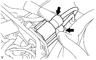 |
Remove the 2 frame wire connectors from the inverter with converter assembly.
| 26. REMOVE CONVERTER WITH INVERTER ASSEMBLY |
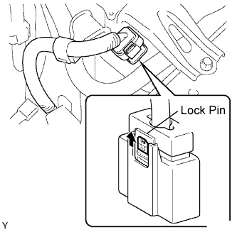 |
Using a small screwdriver, lift up the lock pin (green) as illustrated to unlock it.
Disconnect the connector for the air conditioning inverter.
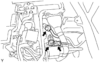 |
Disconnect the 3 connectors shown in the illustration.
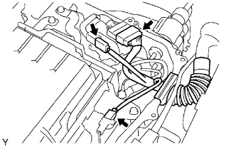 |
Disconnect the 3 connectors shown in the illustration and the engine main wire harness.
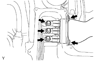 |
Remove the 5 bolts, then disconnect the MG2 power cable.
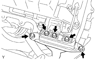 |
Remove the 5 bolts, then disconnect the MG1 power cable.
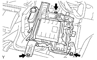 |
Remove the 3 bolts and the inverter with converter assembly.
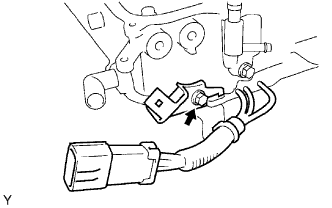 |
Disconnect the connector for the air conditioning inverter from the bracket.
Remove the bolt and connector bracket for the air conditioning inverter.
| 27. REMOVE AIR FUEL RATIO SENSOR (for Bank 1 Sensor 1) |
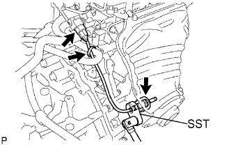 |
Remove the wire harness clamp from the air fuel ratio sensor.
Disconnect the air fuel ratio sensor connector.
Using SST, remove the air fuel ratio sensor.