Home › SUSPENSION & AXLE › AXLE › REAR AXLE HUB AND BEARING

REAR AXLE HUB AND BEARING > INSTALLATION

for Preparation Click here


HINT:
  1. Use the same procedures for the RH side and LH side.
  2. The procedures listed below are for the LH side.


1. INSTALL REAR AXLE HUB AND BEARING ASSEMBLY LH
  1. Install the axle hub and bearing LH on the axle beam with the 4 bolts.

    Torque:
    61 N*m{ 622 kgf*cm , 45 ft.*lbf }


2. CONNECT SKID CONTROL SENSOR CONNECTOR


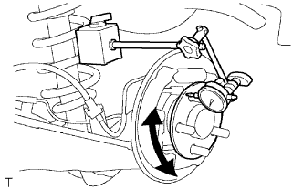
3. INSPECT REAR AXLE HUB BEARING LOOSENESS


    F046836E01
  1. Remove the rear wheel.

  1. Remove the rear brake drum.

    HINT:
    Put matchmarks on the rear brake drum and hub bolt.

  1. Using a dial indicator, check for looseness at the center of the axle hub.

    Maximum looseness:
    0.05 mm (0.0020 in.)

    If the looseness exceeds the maximum, replace the axle hub.


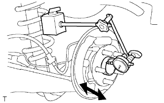
4. INSPECT REAR AXLE HUB BEARING RUNOUT


    F046837E01
  1. Using a dial indicator, check for runout of the axle hub.

    Maximum runout:
    0.07 mm (0.0028 in.)

    If the runout exceeds the maximum, replace the axle hub.

  1. Install the rear brake drum.

    HINT:
    Align the matchmarks of the rear brake drum and hub bolt before installing them.

  1. Install the rear wheel.

    Torque:
    103 N*m{ 1,050 kgf*cm , 76 ft.*lbf }


5. INSTALL REAR BRAKE DRUM SUB-ASSEMBLY


6. INSTALL REAR WHEEL

Torque:
103 N*m{ 1,050 kgf*cm , 76 ft.*lbf }


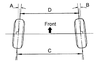
7. INSPECT REAR WHEEL ALIGNMENT


SA03213E02

Standard toe-in:
Item
Specified Condition
Toe-in
(total)
A + B: 0° 18' +-15' (0.30° +-0.25°)
C - D: 3.0 +-2.5 mm (0.12 +-0.10 in.)

HINT:
  1. Measure "C - D" only when "A + B'" cannot be measured.
  2. If the toe-in is not within the specified range, inspect the suspension parts for damage and/or wear, and replace them if necessary.


8. CHECK ABS SPEED SENSOR SIGNAL