 |
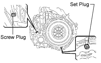
Install a new gasket and the set plug.
- Torque:
- 39 N*m{ 400 kgf*cm , 29 ft.*lbf }
HYBRID VEHICLE TRANSAXLE UNIT > REASSEMBLY |
| 1. INSTALL TRANSAXLE HOUSING AND CASE WITH HEAD STRAIGHT SCREW PLUG |
|
Install a new gasket and the set plug.
Apply liquid sealant 1344 to the first 2 to 3 threads from the end of the screw plug.
Using a 6 mm socket hexagon wrench, install the screw plug.
| 2. INSTALL TRANSAXLE HOUSING AND CASE WITH HEAD STRAIGHT SCREW PLUG |
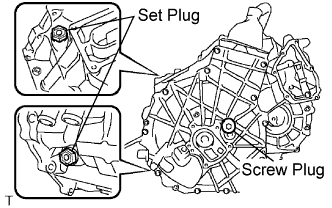 |
Install a new gasket and the set plug.
Apply liquid sealant 1324 to the first 2 to 3 threads from the end of the screw plug.
Using a 10 mm socket hexagon wrench, install the screw plug.
| 3. INSTALL HYBRID TRANSAXLE OIL SEAL RH |
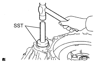 |
Using SST, tap in a new oil seal.
Coat the lip of the oil seal with No. 2 MP grease.
| 4. INSTALL HYBRID TRANSAXLE TYPE T OIL SEAL LH |
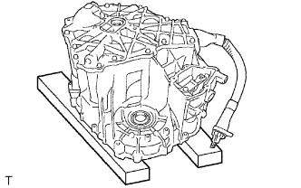 |
Place the motor on wooden blocks or equivalent.
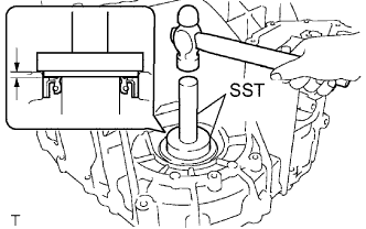 |
Using SST, tap in the oil seal.
Coat the lip of the oil seal with MP grease.
| 5. ADJUST PRELOAD |
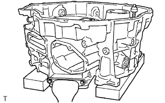 |
Adjust the differential case preload.
Place the motor on wooden blocks or equivalent.
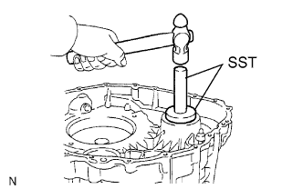 |
Using SST, tap in the differential case tapered roller bearing LH outer race and shim to the motor.
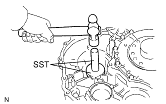 |
Using SST, tap in the differential case tapered roller bearing RH outer race to the generator.
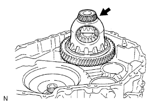 |
Apply ATF WS to the sliding surfaces of the differential case tapered roller bearing and install the bearing to the motor.
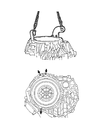 |
Using an engine sling device and chain block, install the motor to the generator.
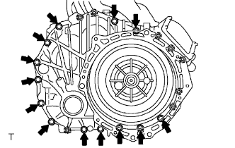 |
Tighten the 13 bolts in the positions shown in the illustration.
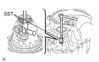 |
Using SST, rotate the differential case in both directions to stabilize the bearings.
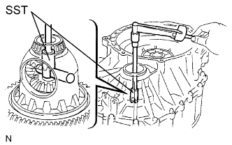 |
Using SST, measure the differential preload of the differential case and rotation torque.
| Part No. | Thickness | Mark |
| 90564-45040 | 1.80 mm (0.0709 in.) | 1 |
| 90564-45041 | 1.83 mm (0.0720 in.) | 2 |
| 90564-45042 | 1.86 mm (0.0732 in.) | 3 |
| 90564-45043 | 1.89 mm (0.0744 in.) | 4 |
| 90564-45071 | 1.92 mm (0.0756 in.) | 50 |
| 90564-45072 | 1.94 mm (0.0764 in.) | 51 |
| 90564-45073 | 1.96 mm (0.0772 in.) | 52 |
| 90564-45074 | 1.98 mm (0.0780 in.) | 53 |
| 90564-45075 | 2.00 mm (0.0787 in.) | 54 |
| 90564-45076 | 2.02 mm (0.0795 in.) | 55 |
| 90564-45077 | 2.04 mm (0.0803 in.) | 56 |
| 90564-45078 | 2.06 mm (0.0811 in.) | 57 |
| 90564-45079 | 2.08 mm (0.0819 in.) | 58 |
| 90564-45080 | 2.10 mm (0.0827 in.) | 59 |
| 90564-45081 | 2.12 mm (0.0835 in.) | 60 |
| 90564-45082 | 2.14 mm (0.0843 in.) | 61 |
| 90564-45083 | 2.16 mm (0.0850 in.) | 62 |
| 90564-45084 | 2.18 mm (0.0858 in.) | 63 |
| 90564-45085 | 2.20 mm (0.0866 in.) | 64 |
| 90564-45086 | 2.22 mm (0.0874 in.) | 65 |
| 90564-45087 | 2.24 mm (0.0882 in.) | 66 |
| 90564-45088 | 2.26 mm (0.0890 in.) | 67 |
| 90564-45089 | 2.28 mm (0.0898 in.) | 68 |
| 90564-45090 | 2.30 mm (0.0906 in.) | 69 |
| 90564-45091 | 2.32 mm (0.0913 in.) | 70 |
| 90564-45060 | 2.34 mm (0.0921 in.) | 19 |
| 90564-45061 | 2.37 mm (0.0933 in.) | 20 |
| 90564-45011 | 2.40 mm (0.0945 in.) | No indication |
| 90564-45062 | 2.43 mm (0.0957 in.) | 22 |
| 90564-45063 | 2.46 mm (0.0969 in.) | 23 |
Using an engine sling device and chain block, remove the 13 bolts and generator.
| 6. INSTALL DIFFERENTIAL DRIVE PINION |
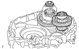 |
Install the differential drive pinion.
| 7. SELECT SHIM |
Select the input shaft shim.
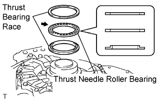 |
Install the No. 1 thrust bearing race.
Apply ATF WS to the sliding surfaces of the thrust needle roller bearing and install the flange bearing.
Install the thrust bearing race.
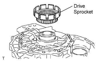 |
Install the drive sprocket.
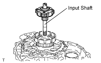 |
Install the input shaft.
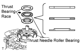 |
Install the No. 1 thrust bearing race.
Apply ATF WS to the sliding surfaces of the thrust needle roller bearing and install the flange bearing.
Install the thrust bearing race.
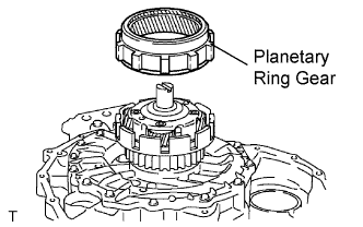 |
Install the planetary ring gear.
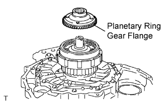 |
Install the planetary ring gear flange.
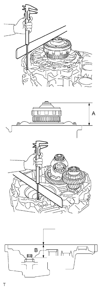 |
Using a straightedge and vernier caliper, measure dimension A as shown in the illustration.
Using a straightedge and vernier caliper, measure dimension B as shown in the illustration.
Select a shim.
| Part No. | Thickness | Mark |
| 90564-36021 | 1.00 mm (0.0394 in.) | 1 |
| 90564-36022 | 1.20 mm (0.0472 in.) | 2 |
| 90564-36023 | 1.40 mm (0.0551 in.) | 3 |
| 90564-36024 | 1.60 mm (0.0630 in.) | 4 |
| 90564-36025 | 1.80 mm (0.0709 in.) | 5 |
| 90564-36026 | 2.00 mm (0.0787 in.) | 6 |
| 90564-36027 | 2.20 mm (0.0866 in.) | 7 |
| 90564-36028 | 2.40 mm (0.0945 in.) | 8 |
| 90564-36029 | 2.60 mm (0.1024 in.) | 9 |
| 90564-36030 | 2.80 mm (0.1102 in.) | 10 |
| 90564-36031 | 3.00 mm (0.1181 in.) | 11 |
| 90564-36032 | 3.20 mm (0.1260 in.) | 12 |
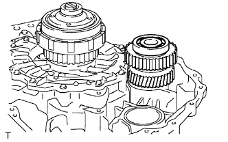 |
Select a counter drive gear shim.
Install the counter drive gear.
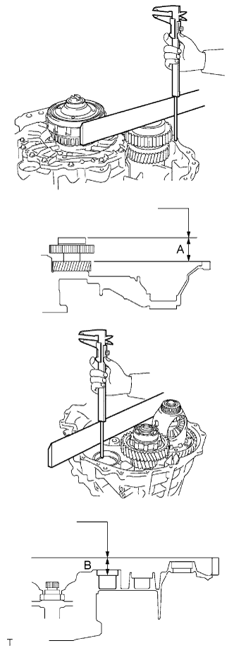 |
Using a straightedge and vernier caliper, measure dimension A as shown in the illustration.
Using a straightedge and vernier caliper, measure dimension B as shown in the illustration.
Select a shim.
| Part No. | Thickness | Mark |
| 90564-35132 | 2.20 mm (0.0866 in.) | A |
| 90564-35133 | 2.25 mm (0.0886 in.) | B |
| 90564-35134 | 2.30 mm (0.0906 in.) | C |
| 90564-35135 | 2.35 mm (0.0925 in.) | D |
| 90564-35136 | 2.40 mm (0.0945 in.) | E |
| 90564-35137 | 2.45 mm (0.0965 in.) | F |
| 90564-35138 | 2.50 mm (0.0984 in.) | G |
| 90564-35139 | 2.55 mm (0.1003 in.) | H |
| 90564-35140 | 2.60 mm (0.1024 in.) | J |
| 90564-35141 | 2.65 mm (0.1043 in.) | K |
| 90564-35142 | 2.70 mm (0.1063 in.) | L |
| 90564-35143 | 2.75 mm (0.1083 in.) | M |
| 90564-35144 | 2.80 mm (0.1102 in.) | N |
| 8. INSTALL INPUT SHAFT ASSEMBLY |
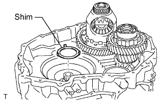 |
Install the shim selected.
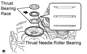 |
Install the planetary ring gear flange.
Install the thrust bearing race.
Install the thrust needle roller bearing.
Apply ATF WS to the sliding surfaces of the thrust needle roller bearing and install the flange.
Install the thrust bearing race.
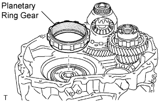 |
Install the planetary ring gear.
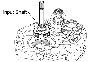 |
Install the input shaft.
| 9. INSTALL SPROCKET DRIVEN GEAR AND COUNTER DRIVE GEAR |
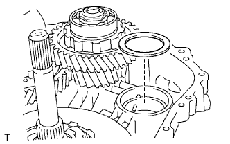 |
Install the counter drive gear shim selected.
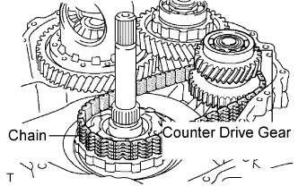 |
Install the counter drive gear and chain.
| 10. INSTALL TRANSMISSION DRIVE SPROCKET SUB-ASSEMBLY |
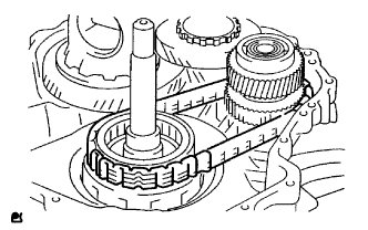 |
Apply ATF WS auto fluid to the drive sprocket needle roller bearing and put the drive sprocket on the chain.
Align the recesses of the planetary ring gear and the drive sprocket and install the drive sprocket with chain.
| 11. INSTALL NO. 2 THRUST BEARING RACE |
Install the thrust bearing race.
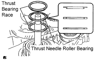 |
Install the No. 1 drive sprocket thrust needle roller bearing.
Apply ATF WS to the sliding surfaces of the thrust needle roller bearing and install the bearing.
Install the No. 2 thrust bearing race.
| 12. INSTALL TRANSMISSION OIL STRAINER |
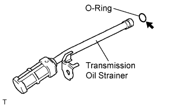 |
Apply ATF WS to a new O-ring and install the fluid strainer.
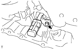 |
Install the oil strainer with the bolt.
| 13. INSTALL HYBRID VEHICLE GENERATOR ASSEMBLY |
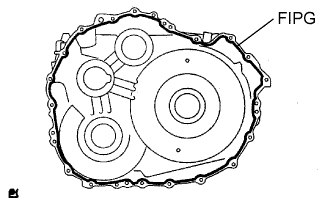 |
Apply seal packing in a continuous line of beads (diameter 1.5 mm, 0.059 in.) to the motor side.
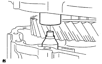 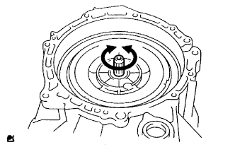 |
Using an engine sling device and chain block, install the parking lock rod to the generator so that it is inserted into the cam guide sleeve.
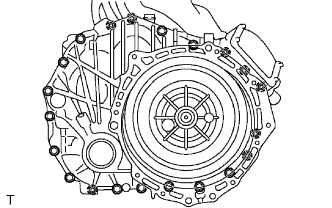 |
Apply adhesive to the first 2 to 3 threads of the bolt end.
Install the 21 bolts as shown in the illustration.
| 14. INSTALL HYBRID VEHICLE TRANSAXLE ASSEMBLY TYPE T OIL SEAL |
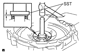 |
Coat the lip of a new oil seal with MP grease.
Using SST, tap in oil seal.
| 15. FIX HYBRID VEHICLE TRANSAXLE ASSEMBLY |
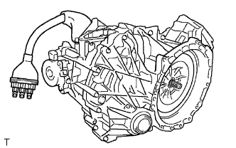 |
Set the hybrid transaxle as shown in the illustration.
| 16. INSTALL PARKING COVER |
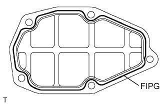 |
Apply seal packing in a continuous line of beads (diameter 1.5 mm, 0.06 in.) as shown in the illustration.
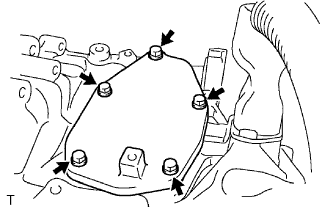 |
Install the parking shaft cover with the 5 bolts.
| 17. INSTALL MOTOR WATER JACKET COVER |
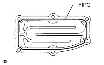 |
Apply seal packing black in a continuous line of beads (diameter 1.5 mm, 0.06 in.) as shown in the illustration.
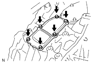 |
Apply adhesive to the first 2 to 3 threads of each of the 6 bolts. Install the motor water jacket cover with the 6 bolts.
| 18. INSTALL TRANSAXLE HOUSING TUBE CONNECTOR |
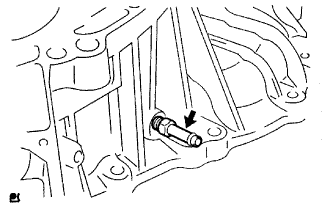 |
Apply adhesive to the first 2 to 3 threads of the bolt and install.
Install the drain plug using a new gasket.
| 19. INSTALL MANUAL DETENT SPRING SUB-ASSEMBLY |
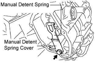 |
Install the manual detent spring and manual detent spring cover with the bolt.
| 20. REMOVE PARKING COVER |
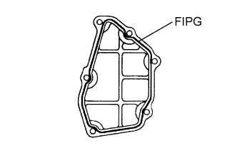 |
Apply seal packing in a continuous line of beads (diameter 1.5 mm, 0.06 in.) as shown in the illustration.
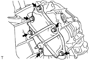 |
Install the parking cover with the 6 bolts.
| 21. INSTALL SHIFT CONTROL ACTUATOR ASSEMBLY |
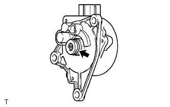 |
Apply a small amount of genuine ATF WS to the O-ring.
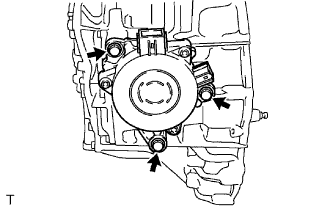 |
Install the shift control actuator with the 3 bolts.
Install the transmission case cover with the 3 bolts.
| 22. INSTALL OIL PUMP DRIVE SHAFT |
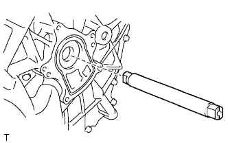 |
Apply ATF WS to the fluid pump drive shaft and install it.
| 23. INSTALL OIL PUMP DRIVEN ROTOR |
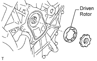 |
Apply ATF WS to the fluid pump driven rotor and install it.
| 24. INSTALL TRANSAXLE OIL PUMP DRIVE ROTOR |
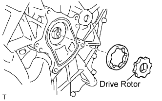 |
Apply ATF WS to the transaxle fluid pump drive rotor and install it.
| 25. INSTALL TRANSMISSION OIL PUMP COVER SUB-ASSEMBLY |
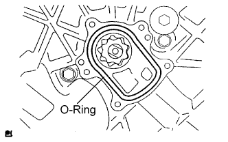 |
Install a new O-ring.
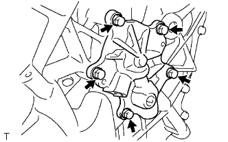 |
Apply adhesive to the first 2 to 3 threads of the bolt end.
Install the oil pump cover with the 5 bolts.
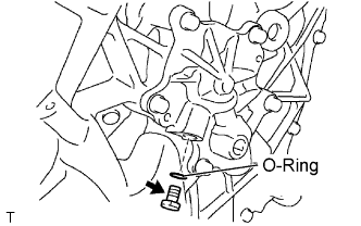 |
Install a new O-ring and fluid pump cover plug.
| 26. INSTALL MOTOR STATOR WIRING HARNESS CONNECTOR |
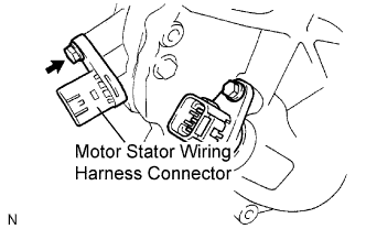 |
Apply ATF WS to the O-ring and install the motor stator wiring harness connectors (black) with the bolt.
| 27. INSTALL MOTOR REVOLUTION SENSOR WIRING HARNESS CONNECTOR |
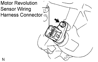 |
Apply ATF WS to the O-ring and install the HV motor side motor revolution sensor wiring harness connectors (gray) with the bolt.
| 28. INSTALL GENERATOR MOTOR REVOLUTION SENSOR WIRING HARNESS CONNECTOR |
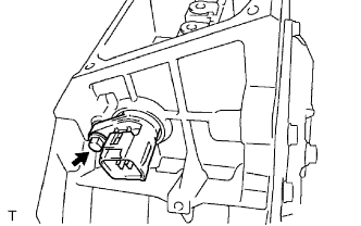 |
Apply ATF WS to the O-ring and install the HV generator side generator motor revolution sensor wiring harness connector with the bolt.
| 29. INSTALL GENERATOR CABLE |
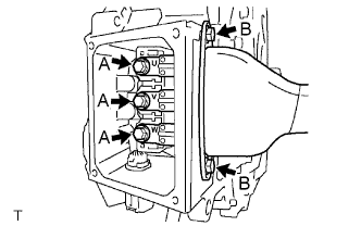 |
Align the generator cables as shown in the illustration and connect them.
Apply adhesive to the first 2 or 3 threads of bolts B and install the generator cable with the bolts.
Install the generator cable with the 3 bolts (A).
| 30. INSTALL POWER CABLE COVER |
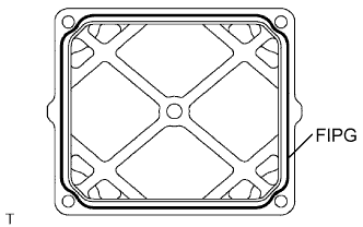 |
Apply seal packing in a continuous line of beads (diameter 1.5 mm, 0.06 in.) as shown in the illustration.
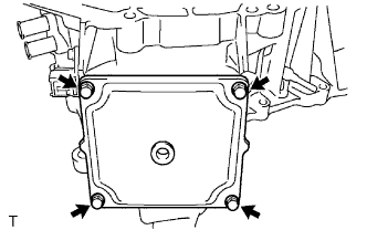 |
Apply adhesive to the first 2 or 3 threads of the 4 bolts and install the power cable cover.
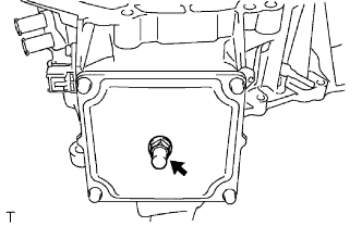 |
Install the breather plug.
| 31. INSTALL NO. 3 ENGINE MOUNTING BRACKET |
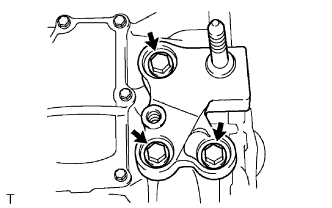 |
Apply adhesive to the first 2 or 3 threads of the 3 bolts and install the engine mounting bracket.
| 32. INSTALL HYBRID VEHICLE TRANSAXLE ASSEMBLY |