 |
Inspect the resistance.
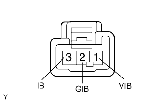
Measure the resistance between terminals 1 (VIB) and 2 (GIB).
- Standard resistance:
Tester Connection Resistance Positive probe to terminal 1 (VIB)
Negative probe to terminal 2 (GIB)3.5 to 4.5 kΩ Positive probe to terminal 2 (GIB)
Negative probe to terminal 1 (VIB)5 to 7 kΩ
Measure the resistance between terminals 1 (VIB) and 3 (IB).
- Standard resistance:
Tester Connection Resistance Positive probe to terminal 1 (VIB)
Negative probe to terminal 3 (IB)3.5 to 4.5 kΩ Positive probe to terminal 1 (VIB)
Negative probe to terminal 3 (IB)5 to 7 kΩ
Measure the resistance between terminals 2 (GIB) and 3 (IB).
- Standard resistance:
- 0.2 kΩ or less
- NOTICE:
- Even if the probes are changed around, the resistance will not vary.